
Specifications


Chapter 3
– 25 – PCI-1710 series User’s Manual
Advantech Co., Ltd.
www.advantech.com
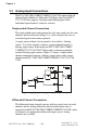
I/O Connector Signal Description
Table 3-1: I/O Connector Signal Description
Signal Name Reference Direction Description
AI<0...15> AIGND Input
Analog Input Channels 0 through 15.
Each
channel pair, AI<i, i+1> (i = 0, 2, 4...14), can be
configured as either two single-ended inputs or
one differential input of PCI-1710/1710L/
1710HG/1710HGL/1716/1716L.
AIGND - -
Analog Input Ground.
The three ground
references (AIGND, AOGND, and DGND) are
connected together on the PCI-1710/1710L/
1710HG/1710HGL/1711/1711L/1716/1716L card.
AO0_REF
AO1_REF
AOGND Input
Analog Output Channel 0/1 External Reference.
AO0_OUT
AO1_OUT
AOGND Output
Analog Output Channels 0/1.
AOGND - -
Analog Output Ground.
The analog output
voltages are referenced to these nodes. The three
ground references (AIGND, AOGND, and DGND)
are connected together on the PCI-1710/1710L/
1710HG/1710HGL/1711/1711L/1716/1716L card.
DI<0..15> DGND Input
Digital Input channels.
DO<0..15> DGND Output
Digital Output channels.
DGND - -
Digital Ground.
This pin supplies the reference
for the digital channels at the I/O connector as
well as the +5VDC supply. The three ground
references (AIGND, AOGND, and DGND) are
connected together on the PCI-1710/1710L/
1710HG/1710HGL/1711/1711L/1716/1716L card.
CNT0_CLK DGND Input
Counter 0 Clock Input.
The clock input of counter
0 can be either external or internal , as set by
software.
CNT0_OUT DGND Output
Counter 0 Output.
CNT0_GATE DGND Input
Counter 0 Gate Control.
PACER_OUT DGND Output
Pacer Clock Output.
This pin pulses once for
each pacer clock when turned on. If A/D
conversion is in the pacer trigger mode, users
can use this signal as a synchronous signal for
other applications. A low- to- high edge triggers
A/D conversion to start.
TRG_GATE DGND Input
A/D External Trigger Gate.
When TRG _GATE is
connected to +5 V, it will enable the external
trigger signal to input. When TRG _GATE is
connected to DGND, it will disable the external
trigger signal to input.
EXT_TRG DGND Input
A/D External Trigger.
This pin is external trigger
signal input for the A/D conversion. A low-to-high
edge triggers A/D conversion to start.
+12V DGND Output
+12 VDC Source.
+5V DGND Output
+5 VDC Source.