
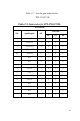
Specifications


115
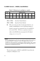
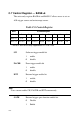
? BASE+4 bit 3 to bit 0, STA3 ~ STA0, hold the start scan channel
number.
? BASE+5 bit 3 to bit 0, STO3 ~ STO0, hold the stop scan channel
number.
Writing to these two registers automatically initializes the scan range
of the Multiplexer. Each A/D conversion trigger also sets the
Multiplexer to the next channel. With continuous triggering, the
Multiplexer will scan from the start channel to the stop channel and
then repeat. The following examples show the scan sequences of the
Multiplexer.
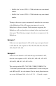
Example 1
If the start scan input channel is AI3 and the stop scan input channel
is AI7, then the scan sequence is AI3, AI4, AI5, AI6, AI7, AI3, AI4,
AI5, AI6, AI7, AI3, AI4…
Example 2
If the start scan channel is AI13 and the stop scan channel is AI2,
then the scan sequence is AI13, AI14, AI15, AI0, AI1, AI2, AI13,
AI14, AI15, AI0, AI1, AI2, AI13, AI14...
The scan logic of the PCI-1710/1710L/1710HG/1710HGL/1716/
1716L card is powerful and easily understood. You can set the gain
code, B/U and S/D, for each channel. For the Analog Input function,
we set two AI channel AI<i, i+1> ( i= 0, 2, 4, ...,14) work as a pair.