32-bit LabVIEW Drivers User’s Guide (Windows 95&98/NT/2000 Version) 2st Edition December,25 2000 S/N:2053000201 Advantech Corporation
Table of Contents About this manual Chap 1 Installation and Configuration 1.1 Installation 1.2 Configuration Chap 2 Tutorials 2.1 Search for examples 2.2 Build a Virtual Instrument 2.3 Tutorials 2.3.1 Tutorial 1: Get voltage input from PCL-818 2.3.2 Tutorial 2: Get digital input from PCL-818 2.3.3 Tutorial 3: Programming with Advantech EASY I/O VIs 2.3.4 Tutorial 4: Error handling for error message Chap 3 EASY I/O VIs 3.1 Select Pop 3.2 EasyFastAI Chap 4 Advanced I/O VIs 4.1 Function flow overview 4.
About This Manual The LabView for Windows Data Acquisition and Control VI(Virtual Instrument) user manual describes the VIs that support Advantech plug-in data acquisition and control cards and field-bus data acquisition and control modules. In order to efficiently link Advantech data acquisition and control (DA&C) devices with LabView to develop your DA&C application, you should be familiar with the operation of LabView, your computer, your computer’s operating system, and your DA&C hardware.
Install DLL and LabVIEW drivers The Tutorial sections will guide you through the several steps of installation and configuration to set up DLL drivers and LabVIEW drivers. DLL drivers should be installed and configured before LabVIEW drivers. For detailed information, please refer to chapter 1 Installation and Configuration. Run tutorials The Tutorial sections in this chapter will guide you through a simple example VIs for each functional area.
Chapter 1 Installation and Configuration This manual describes Advantech’s 32-bit LabVIEW driver designed to integrate Advantech PC-LabCards and remote data acquisition and control devices with LabVIEW software. These drivers will be executed in Microsoft Windows 95 and Windows NT 4.0 environments. 32-bit LabVIEW drivers feature with both high speed and normal speed data acquisition functions and provide two different interfaces set for users.
Advantech’s 32-bit LabVIEW drivers provide two different sets of VIs: Easy I/O VIs and Advanced I/O VIs. The Easy I/O VIs are a collection of I/O blocks which are used to perform basic I/O operations. The Advanced I/O VIs are more flexible than the Easy I/O VIs, at the cost of complexity.
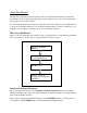
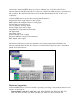
- PCL-812PG, PCL-813B, PCL-816, PCL-818, PCL-818H/HD/HG/L/LS, PCL-833, PCL-836,PCI-1750/1751/1710/1710HG/1720/1760/1712/1713/1753/1752/1754/1756/1711/1731 PCM series modules: PCM-3718, PCM-3724 MIC series modules: MIC-2718/2728/2730/2732/2750/2752 ADAM-4000 and ADAM-5000/485 series modules LabVIEW Software Other Drivers Other Hardware Advantech LabVIEW Drivers Advantech PCLS-DLL Drivers Advantech DA&C H/W 1.1 Installation Installing Advantech DLL (PCLS-DLL) drivers 1.
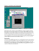
2. From Program Manager, switch to LabVIEW driver directory and select “SETUP.EXE” file. Double click the mouse button to run it. 3. Supply the information required by the installation program. The setup program will install all required files to the HDD and the directory you specified. An example program is also installed in a subdirectory of the LabVIEW driver software. The default directory is "C:\LABVIEW\ EXAMPLES \ADVANTECH". 4.
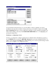
You can install as many I/O devices as you want. When you have completed your device installation and setup, there should be a listing reflecting your installation displayed in the I/O Device Installation dialog box. Once an I/O device installed, you may change its parameters by either double clicking on its entry in the INSTALLED DEVICES list box, or highlighting and pressing the Setup button.
Configure the device, and when you're satisfied with your entries, press OK. This will bring you back to the I/O Device Installation dialog box, where you can see a displayed list (Installed Devices) reflecting your I/O device configuration. Adding a device To Add and set up each I/O device in the Device Installation program, go into the SETUP menu, and click DEVICE.
Chapter 2 Tutorials This chapter teaches you step-by-step how to create an application in LabVIEW. It also guides you through the Search Examples feature to help you find examples in LabVIEW. You will learn to do the following: - Use the Search Examples feature to find and run an example - Create a new program in LabVIEW The VI you build generates data, analyzes it, then writes it to a file. Tip: For more detailed information, please refer to examples in the directory path LabVIEW\Examples\Advantech.
6. Create a waveform chart by selecting Controls>>Graph>>Waveform Chart. This chart plots data one point at a time. 7. Place the chart on the front panel and label it Random Plot. 8. To change the scale of the waveform chart, select the Operating tool from the Tools palette. If the Tools palette is not visible, select Windows>>Show Tools Palette. Double-click 10.0 on the Y-axis of the Random Plot indicator and enter new scale value.
2.3 Tutorials 2.3.1 Tutorial 1 : Get voltage input from PCL-818L The purpose of this tutorial is to teach you how to build a LabVIEW application to retrieve voltage input values from Advantech PCL-818L data acquisition and control cards through Advantech 32-bit LabVIEW driver. 1. Click “New VI” button to create a new LabVIEW program 2. Select Front Panel and enable Controls Palette to choose a “Waveform Chart” indicator in “Graph” group, add to front panel and name it “Voltage”. 3.
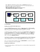
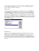
4. Add a “DeviceOpen” VI from the Advantech 32-bit LabVIEW driver by clicking on user defined VIs. The path to get “DeviceOpen” VI is “User Defined VIs” >> “Advantech” >> “Advance” >> “DeviceManager” >> “DeviceOpen”.
5. Move the mouse to the “DeviceOpen” VI and click on the mouse left button to invoke the “Create Constant” function. After creating a constant, a number will appear at the left of “DeviceOpen” VI block. 6. Execute the Advantech device installation utility (within Advantech DLL driver) from the Windows environment to check with the device number of Advantech DEMO I/O virtual demo board. For example, the device number of Advantech DEMO I/O in the screen shown below is 001. 7.
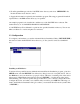
9. Add “DeviceClose” VI from the Advantech 32-bit LabVIEW driver by clicking on User Defined VIs. The path to get “DeviceClose” VI is “User Defined VIs” >> “Advantech” >> “Advance” >> “DeviceManager” >> “DeviceClose”. 10.Change the mouse cursor for use with the “Wiring” pattern (move the cursor into Tools Palette and select the Wiring icon). 11.Wire the DeviceHandle output of the DeviceOpen VI to the DeviceHandle input of AIConfig VI. To make wiring easier, you can invoke the Help window to support it.
12.Wire the DeviceHandle output of the AIConfig VI to the DeviceHandle input of AIVoltageIn VI.Wire the DeviceHandle output of AIVoltageIn VI to the DeviceHandle input of the DeviceClose VI. Wire the Voltage output of the AIVoltageIn VI to the Voltage data terminal. 13.For the AIConfig VI, “Channel” and “Gain” are necessary input values.
14.After enabling the Block Diagram, you will find a “Chan&Gain” data terminal displayed on the Block Diagram. Wire the output of the “Chan&Gain” data terminal to the input “Chan&Gain” of the AIConfig VI.
15.The basic steps to get AIVoltageIn data are now complete. You can change the window to the Front Panel window and click the “Run” or “Run Continuously” button to execute AIVoltageIn VI. 16.If your waveform chart does not show the whole graph, you can change the scale of the Y-axis. To change the Y axis scale on the waveform chart, move the cursor to the graphic origin, click the left mouse button, and type in the desired value.
17.The “Run Continuously” button executes the AIVoltageIn VI continuously. You can also add a “While Loop” to enhance your program. First, move mouse to Functions Palette and select the Structures group and the While Loop VI. Add the While Loop VI to the Block Diagram and enlarge it to include the AIVoltageIn VI and the Voltage data terminal. 18.Add a Stop button to control the execution of the While Loop. Enable the Front Panel and move the mouse to Controls Palette.
between TF VI and COND VI. 20.Wire the output of the TF VI to the input of the NOT VI and wire the output of the NOT VI to the input of the COND VI. After wiring, switch to Front Panel and press the RUN button to execute. 21.If you want to get voltage data from a given device, just change the constant number of the DeviceOpen VI to be the device number of the device of interest. For example, the device number of the PCL-818 in this tutorial is 0.
2.3.2 Tutorial 2: Get Digital Input Data from PCL-818 The purpose of this tutorial is to teach you how to build a LabVIEW application to retrieve digital input values from Advantech PCL-818L data acquisition and control cards through an Advantech 32-bit LabVIEW driver. 1. Click “New VI” button to create a new LabVIEW program 2. Switch to Block Diagram. Add the “DeviceOpen” and the “DeviceClose” VIs from Advanced VIs and the “DeviceManager” group.
4. Move the Round LED icon into the Array icon and enlarge the Array icon to contain 8 round LEDs. 5. Switch to the Block Diagram window. You will find the TF data terminal (named Digital Input) mapped to the Round LED icon. Add a NumbertoBinaryArray VI from the Boolean group in the Functions Palette.
6. Create a constant for the device number of the DeviceOpen VI. Create another constant for the port of the DIOReadPortByte VI. 7. Wire the DeviceHandle output of the DeviceOpen VI to the DeviceHandle input of the DIOReadPortByte VI. Wire the DeviceHandle output of the DIOReadPortByte VI to the DeviceHandle input of DeviceClose VI. Wire the state output of the DIOReadPortByte VI to the input of NumbertoBinaryArray VI. Wire the output of NumbertoBinaryArray VI to the input of TF data terminal.
8. Compare the device number of the Advantech DEMO I/O with the device number value of the DeviceOpen VI. After checking, press the Run button to execute this tutorial.
2.3.3 Tutorial 3: Programming with Advantech EASY I/O VIs The purpose of this tutorial is to teach you how to build a LabVIEW application through EASY I/O VIs to retrieve digital input value from Advantech PCL-818L data acquisition and control cards. 1. First, you can open “Tutor1.vi” to continue with Tutorial 1 “Get voltage input from PCL-818L”. If you did not do Tutorial 1, please refer to Tutorial 1 to implement “Tutor1.vi” 2. After opening “Tutor1.
In Tutorial 1, you have to assign a constant value for the device number of the DeviceOpen VI before executing Tutorial 1. That means, you can not change the device while Tutorial 1 is executing. Now, you can use the SelectDevicePop VI from EASY I/O VIs to select the device during execution. 3. Switch to the Block Diagram window. Move the mouse to the Tools palette and select indicator mode for the cursor. 4. Delete the constant number next to the DeviceOpen VI. 5.
6. Now, you can run Tutorial 1 immediately. A pop-up panel will be displayed on screen for selecting devices. 7. Proceed as in step 5 to add the SelectChanPop VI and the SelectGainPop VI. Due to parameter transformation of channel and gain data, you will need to add the “Unbundled by Name” VI for retrieving channel values from “channel info” parameter and a “Bundled” VI to combine channel and gain codes into a cluster “chan&gain” for the AIConfig VI.
8. Press the “Run” button to execute the tutorial 3 program.
2.3.4 Tutorial 4. Error handling for error message The purpose of this tutorial is to teach you how to apply the error handling function (error in and error out) of each Advantech VI to debug your program. 1. First, you can open “Tutor2.vi” to continue with Tutorial 2 “Get voltage input from PCL-818L”. If you did not do Tutorial 2, please refer to Tutorial 2 to implement “Tutor2.vi”. 2. Wire the error out parameter of the DeviceOpen VI to the error in parameter of the DIOReadPortByte VI.
4. Switch to the Block Diagram window. You will find the Error Message data terminal added to the Block Diagram. Move the data terminal to the end of the DeviceClose VI. Insert an UnbundledByName VI between the DeviceClose VI and the ErrorMessage data terminal and wire the error out parameter to the input of the UnbundledByName VI. 5. Move the cursor to the UnbundledByName VI and click on the right button of the mouse to invoke the Selectitem option.
6. Wire the output of the UnbundledByName VI to the input of the ErrorMassge data terminal to display messages in the Front Panel. 7. Press the Run button to execute Tutorial 4 program. You will find that the Error Message block at the Front Panel is blank. But if you delete the wiring between the DeviceOpen VI and the DIOReadPortByte VI, you will get an error message in the Error Message block.
Chapter 3 Easy I/O VIs This chapter contains reference descriptions of the EASY I/O VIs, which perform simple channel/device operations and Fast AI channel operations. You can use these VIs from the front panel or use them as subVIs in basic applications. The EASY I/O VIs are actually composed of intermediate VIs, which are in turn composed of advanced VIs. The EASY I/O VIs provide a simple, convenient interface with only the most commonly used inputs and outputs.
Easy I/O VI Descriptions 3.1 SelectPop 3.1.1 SelectDevicePop Displays pop-up panel for selecting an installed device and outputting device number and the number of sub-devices linked to the device. If error occurs, error information will be passed through the error out parameter. Input: None Output: Data type Parameter Description DevNum The device number of the hardware installed in the system by “DEVINST.
3.1.2 SelectSubDevicePop Displays pop-up panel for selecting installed device by its device number, and outputting the module numbers of the expansion device or daughterboard. If error occurs, error information will be passed through error out parameter. Input: Data type Parameter Description DevNum The device number of the hardware installed in the system by “DEVINST.
3.1.3 SelectChannelPop Displays pop-up panel for selecting the channel of an installed device and outputting selected channel information and the gain list of the specified device. If error occurs, error information will be passed through the error out parameter. Input: Data type Parameter Description DevHandle The handler id of the device specified by DevNum as assigned by the LabVIEW program.
3.1.4 SelectGainPop Display pop-up panel for selecting the gain code from a gain list for the device specified at a previous VI. Input: Data type Parameter Description Gain List An array of gain code for the previously specified device. . Parameter Description Gain Code Specifies the gain code for the channel specified above on the DAS I/O device. If the hardware does not support a programmable gain (gain setting by software), this value should be ignored.
3.1.5 GetGainInfo Gets the gain information of the specified device. The device is specified by DevHandle. (You can use DeviceOpen VI to get DevHandle). Gain information includes a string list of gains (such as +/- 5V, +/- 10V, …) and gain codes. Input: Data type Parameter Description DevHandle The handler id of the device specified by DevNum as assigned by the LabVIEW program.
3.1.6 EasyAIPopup Pops up a dialog windows for inputting Analog Input (AI) related configuration data and passes these data to next VI block. Input: None Output: Data type Parameter Description Chan&Gain A cluster data containing Chan Info parameter (includes Channel number, ExpBrdID, and Expchannel data) and Gain code for specified device. DevNum The device number of the hardware installed in the system by “DEVINST.EXE” error out A cluster containing error information.
3.2 EasyFastAI 3.2.1 SingleChannelINTSetup Initiates an asynchronous, single-channel data acquisition operation with interrupt transfer and stores its input in an array. Input: Data type Parameter Description DevHandle The handler id of the device specified by DevNum as assigned by the LabVIEW program. FAIINTStart Initiates an asynchronous, single-channel data acquisition operation with interrupt transfer and stores its input in an array.
3.2.2 SingleChannelDMASetup Initiates an asynchronous, single-channel data acquisition operation with DMA and stores its input in an array. Input: Data type Parameter Description DevHandle The handler id of the device specified by DevNum as assigned by the LabVIEW program. FAIDMAStart FAIDMAStart includes trigsrc, samplerate, chan, gain, buffer, count, Intrcount.
3.2.3 MultiChannelINTSetup Initiates an asynchronous, multiple-channel data acquisition operation with interrupt transfer and stores its input in an array. Input: Data type Parameter Description DevHandle The handler id of the device specified by DevNum as assigned by the LabVIEW program. FAIINTScanStart FAIINTScanStart includes TrigSrc, SampleRate, NumChans, StartChan, GainList, buffer, count, cyclic, FIFOSize.
3.2.4 MultiChannelDMASetup Initiates an asynchronous, multiple-channel data acquisition operation with DMA and stores its input in an array. Input: Data type Parameter Description DevHandle The handler id of the device specified by DevNum as assigned by the LabVIEW program.
3.2.5 MultiChannelDMAExSetup Initiates an asynchronous, multiple-channel data acquisition operation with PCI-Bus mastering DMA and stores its input in an array(only for PCI-1712). Input: Data type Parameter Description DevHandle The handler id of the device specified by DevNum as assigned by the LabVIEW program.
3.2.6 WaitFastAIEvent Waits for FastAI event until specified time has elapsed and outputs the status of the buffer change, terminate, or overrun. Input: Data type Parameter Description DevHandle The handler id of the device specified by DevNum as assigned by the LabVIEW program. Millisec Specifies the time to wait for a FastAI event. The unit of time is milliseconds.
indicated an error, the status, code, and source elements of error out have the same values as the corresponding elements of error in
3.2.7 SingleChanDualDMASetup Initiates an asynchronous, single-channel data acquisition operation with Dual DMA transfer and stores its input in an array. This function supports PCL-1800 only . Input: Data type Parameter Description DevHandle The handler id of the device specified by DevNum as assigned by the LabVIEW program. FAIDualDMAStart FAIDualDMAStart includes TrigSrc, SampleRate, NumChan, StartChan, GainList, BufferA, BufferB, count.
3.2.8 MultiChannelDualDMASetup Initiates an asynchronous, multiple-channel data acquisition operation with Dual DMA transfer and stores its input in an array. This function supports PCL-1800 only . Input: Data type Parameter Description DevHandle The handler id of the device specified by DevNum as assigned by the LabVIEW program. FAIDualDMAScanStart FAIDualDMAScanStart includes TrigSrc, SampleRate, NumChan, StartChan, GainList, BufferA, BufferB, count.
3.2.9 MultiChannelWatchdogINTSetup Initiates an asynchronous data acquisition operation with analog watchdog by interrupt transfer and stores its input in an array Input: Data type Parameter Description DevHandle The handler id of the device specified by DevNum as assigned by the LabVIEW program. FAIINTWatchdogStart FAIINTWatchdogStart includes TrigSrc, SampleRate, buffer, BufferSize, count, cyclic, IntrCount.
3.2.10 MultiChannelWatchdogDMASetup Initiates an asynchronous data acquisition operation with analog watchdog by DMA transfer and stores its input in an array. Input: Data type Parameter Description DevHandle The handler id of the device specified by DevNum as assigned by the LabVIEW program. FAIDMAWatchdogStart FAIDMAWatchdogStart includes TrigSrc, SampleRate, BufferA, BufferB, BufferSize, buffer, count, cyclic .
3.2.11 OverrunHandler Clears overrunning flag. Input: Data type Parameter Description DevHandle The handler id of the device specified by DevNum as assigned by the LabVIEW program. Overrun Overrun status: overrun (1), no overrun (0) error in A cluster containing error information, such as the status, code, and source elements that is passed from a previous linked VI. Parameter Description DevHandle The handler id of the device specified by DevNum as assigned by the LabVIEW program.
3.2.12 BufferChangeHandler Transfers the data from the buffer being used for the data acquisition operation to the specified data buffer Input: Data type Parameter Description DevHandle The handler id of the device specified by DevNum as assigned by the LabVIEW program. BufferChange Indicates whether the data in the buffer is changed or not.
3.2.13 EasyFAICheck Checks whether the single channel data acquisition operation is complete or not and return current status. Input: Data type Parameter Description DevHandle The handler id of the device specified by DevNum as assigned by the LabVIEW program. Count Specifies the buffer size to be transferred error in A cluster containing error information, such as the status, code, and source elements that is passed from a previous linked VI.
3.2.14 SplitIDArray Splits the input array to the output array based on the input NumOfChannel. Input: Data type Parameter Description NumOfChannel While input array contains multiple-channel data, the NumOf Channel is used to specify which data will be output to output array. Input Array The buffer array stores multiple-channel data. Parameter Description Output Array The buffer array stores multiple-channel data.
3.2.15 EasyDualFAICheck Checks whether the asynchronous, multiple-channel data acquisition operation is complete or not and return current status. Input: Data type Parameter Description DevHandle The handler id of the device specified by DevNum as assigned by the LabVIEW program. Count Specifies the buffer size to be transferred error in A cluster containing error information, such as the status, code, and source elements that is passed from a previous linked VI.
Chapter 4 Advanced I/O VIs The Advanced I/O VIs provide more hardware and software functionality, flexibility, and efficiency than the Easy I/O VIs. 4.1 DLL Function Support This chapter contains tables that show the VI functions support for each hardware device.
FAIIntScanStart FAIDMAScanStart FAIDualDMAStart FAIDualScanStart FAITransfer FAICheck FAIIntWatchdogStart FAIDMAWatchdogSta FAIWatchdogCheck FAIStop AllocateDMABuffer FreeDMABuffer FAOIntStart FAODMAStart FAOLoad FAOScale FAOCheck FAOStop EnableEvent CheckEvent Counter functions CounterEventStart CounterEventRead CounterFreqStart CounterFreqRead CounterPulseStart CounterReset QCounterConfig QCounterConfigSys QCounterStart QcounterRead Function Device functions DeviceOpen DeviceClose DeviceGetFeatures Analo
AOVoltageOut AOScale EnableSyncAO WriteSyncAO AOCurrentOut Port I/O functions WritePortByte WritePortWord ReadPortByte ReadPortWord Digital input/output DioGetConfig DioSetPortMode DioReadPortByte DioWritePortByte DioReadBit DioWriteBit DioGetCurrentDOByte DioGetCurrentDOBit Temperature TCMuxRead High-speed functions FAIIntStart FAIDMAStart FAIIntScanStart FAIDMAScanStart FAIDualDMAStart FAIDualScanStart FAITransfer FAICheck FAICheckEvent FAIIntWatchdogStart FAIDMAWatchdogStart FAIWatchdogCheck FAIStop Allo
QcounterRead Function Device functions DeviceOpen DeviceClose DeviceGetFeatures Analog input AIConfig AIGetConfig AIBinaryIn AIScale AIVoltageIn AIVoltageInExp MAIConfig MAIBinaryIn MAIVoltageIn MAIVoltageInExp Analog output AOConfig AOBinaryOut AOVoltageOut AOScale Port I/O functions WritePortByte WritePortWord ReadPortByte ReadPortWord Digital input/output DioGetConfig DioSetPortMode DioReadPortByte DioWritePortByte DioReadBit DioWriteBit DioGetCurrentDOByt DioGetCurrentDOBit Temperature TCMuxRead High-
DeviceClose DeviceGetFeatures Port I/O functions WritePortByte WritePortWord ReadPortByte ReadPortWord Digital input/output DioGetConfig DioSetPortMode DioReadPortByte DioWritePortByte DioReadBit DioWriteBit DioGetCurrentDOByte DioGetCurrentDOBit Counter functions CounterEventStart CounterEventRead CounterFreqStart CounterFreqRead CounterPulseStart CounterReset QCounterConfig QCounterConfigSys QCounterStart QCounterRead High-speed functions EnableEvent CheckEvent Function Device functions DeviceOpen Device
High-speed EnableEvent CheckEvent TimerCountSetting EnableEventEx FDITransfer Counter functions CounterEventStart CounterEventRead CounterFreqStart CounterFreqRead CounterPulseStart CounterReset QCounterConfig QCounterConfigSys QCounterStart QcounterRead √ √ √ √ √ √ √ √ √ √ √ √ √ √ √ √ √ √ √ √ √ √ √ √ √ √ √ √ √ √ √ √ √ √ √ √ √ √ √ √ √ √ √ √ √ √ √ √ √ √ √ √ √ √ √ √ √
Table 4-1.
Function Device functions DeviceOpen DeviceClose DeviceGetFeatures Digital input/output DioGetConfig DioSetPortMode DioReadPortByte DioWritePortByte DioReadBit DioWriteBit DioGetCurrentDOByte DioGetCurrentDOBit Counter functions CounterEventStart CounterEventRead CounterReset Alarm functions AlarmConfig AlarmEnable AlarmCheck AlarmReset Comm. port COMOpen COMClose COMGetConfig COMSetConfig COMRead COMWrite COMWrite232 COMEscape ADAM-4 060/5056 /5060 √ √ √ Table 4-1.
The advanced I/O VIs must be called in the following order: Fig 4-1.
Analog Input Flow Chart: Fig 4-2. Function Flow Overview Analog Output Flow Chart: Fig 4-3.
Digital Input /Output Flow Chart: Fig 4-4. Function Flow Overview Event Counter Flow Chart: Fig 4-5.
Frequency Measurement Flow Chart: Fig 4-6. Function Flow Overview Pulse Output Flow Chart: Fig 4-7.
Quadratic Counter Flow Chart: Fig 4-8.
Alarm Operations Flow Chart: Fig 4-9.
Fig 4-10.
Single channel EnableEvent FAIIntStart CheckEvent No Buffer Full (complete) Yes Yes FAITransfer Repeated? No FAIStop Fig 4-11.
Fig 4-12.
Single channel AllocateDMABuffer EnableEvent FAIDmaStart CheckEvent No Buffer Full (complete) Yes Yes FAITransfer Repeated? No FAIStop FreeDMABuffer Fig 4-13.
Fig 4-14.
Multiple Channel EnableEvent FAIIntScanStart CheckEvent No Buffer Full (complete) Yes Yes FAITransfer Repeated? No FAIStop Fig 4-15.
Fig 4-16.
Multiple Channel AllocateDMABuffer EnableEvent FAIDmaScanStart CheckEvent No Buffer Full (complete) Yes Yes FAITransfer Repeated? No FAIStop FreeDMABuffer Fig 4-17.
Fig 4-18.
Conditional conversion EnableEvent FAIWatchdogConfig FAIIntWatchdogStart CheckEvent No Buffer Full (complete) Yes Yes FAITransfer Repeated? No FAIStop Fig 4-19.
Fig 4-20.
Conditional conversion FAIWatchdogConfig AllocateDMABuffer EnableEvent FAIDmaWatchdogStart CheckEvent No Buffer Full (complete) Yes Yes FAITransfer Repeated? FAIStop FreeDMABuffer Fig 4-21.
Analog Output FAOScale FAODmaStart FAOCheck No Buffer Empty (complete) Yes FAOScale Yes FAOLoad Repeated? No FAOStop Fig 4-22.
Analog Output EnableEvent FAOScale FAOLoad FAODmaStart CheckEvent No Buffer Empty (complete) Yes Yes FAOScale FAOLoad Repeated? No FAOStop
Fig 4-23 The Call Flow for Single-Channel Analog Output with DMA transfer and event function Analog Output FAOScale FAOIntStart FAOCheck No Buffer Empty (complete) Yes Yes FAOScale FAOLoad Repeated? No FAOStop Fig 4-24.
Analog Output FAOScale EnableEvent FAOIntStart CheckEvent No Buffer Empty (complete) Yes Yes FAOScale FAOLoad Repeated? No FAOStop Fig 4-25.
The Advanced I/O VIs are actually composed of intermediate VIs, which are in turn composed of advanced VIs.
adCountTimer adAlarm FastAI FastAO WatchDog COM Port - DIOReadPortByte WritePortByte ReadPortByte WritePortWord ReadPortWord outp outpw inp inpw CounterEventStart CounterEventRead CounterFregStart CounterFregRead QCounterStart QCounterRead CounterPulseStart CounterReset QCounterConfigSys QcounterConfig TimerCountSetting AlarmConfig AlarmEnable AlarmCheck AlarmReset FAIINTStart FAIINTScanStart FAIDMAStart FAIDMAScanStart FAIDualDMAStart FAIDualDMAScanStart FAITransfer FAICheck ClearOverrun FAIStop FAI
PWM ADAMConfig - COMClose COMGetConfig COMSetConfig COMRead COMWrite COMWrite232 COMEscape CounterPWMEnable CounterPWMSetting DICounterReset EnableEventEx FDITransfer PWMStartRead ADAMAIGetHWConfig ADAMAISetHWConfig ADAMAOGetHWConfig ADAMAOSetHWConfig - COMClose - COMGetConfig - COMSetConfig - COMRead - COMWrite - COMWrite232 - COMEscape - DRV_CounterPWMEnable - DRV_CounterPWMSetting - DRV_DICounterReset - DRV_EnableEventEx - DRV_FDITransfer - DRV_PWMStartRead - DRV_ADAMAIGetHWConfig - DRV_ADAMAISetHWCo
4.2. DeviceManager 4.2.1 DeviceGetNumOfList Gets number of the installed devices Input: None Output: Data type Parameter Description NumOfDevices The number of devices installed in the system by “DEVINST.EXE” error out A cluster containing error information.
4.2.2 DeviceGetList Gets a list of the installed devices not including the devices attached to COM ports. Input: None Output: Data type Parameter Description NumOfDev The number of devices installed in the system not including devices attached to COM ports. DevInfoList Specifies the list of the installed devices. error out A cluster containing error information.
4.2.3 DeviceGetSubList Gets a list of the installed devices on COM port. Input: Data type Parameter Description DevNum The device number of the hardware installed in the system by “DEVINST.EXE” Parameter Description DevNum The device number of the hardware installed in the system by “DEVINST.EXE” NumOfSubDev The number of devices expansion hardware installed in the system by “DEVINST.EXE” SubDevInfoList Specifies the list of the installed expansion or daughterboard devices.
4.2.4 BoardName Get the item name of a specified device. Input: Data type Parameter Description BoardID The device id of the hardware installed in the system by “DEVINST.EXE” Parameter Description BoardName The device item name of the hardware installed in the system by “DEVINST.EXE” error out A cluster containing error information.
4.2.5 DeviceOpen Open the device specified by DevNum and installed in the system by “DEVINST.EXE”. Input: Data type Parameter Description DevNum The device number of the hardware installed in the system by “DEVINST.EXE” Parameter Description DevHandle The handler id of the device specified by DevNum as assigned by the LabVIEW program. error out A cluster containing error information.
4.2.6 DeviceClose Close the device specified by DevHandle and installed in the system by “DEVINST.EXE”. Input: Data type Parameter Description DevHandle The handler id of the device specified by DevNum as assigned by the LabVIEW program. error in A cluster containing error information, such as the status, code, and source elements that is passed from a previous linked VI. Parameter Description error out A cluster containing error information.
4.2.7 DeviceGetFeatures This function accepts a device handler id and returns the device features of the specified devices. Input: Data type Parameter Description DevHandle The handler id of the device specified by DevNum as assigned by the LabVIEW program. error in A cluster containing error information, such as the status, code, and source elements that is passed from a previous linked VI.
4.2.8 GetErrorMessage Retrieves an error message specified by an error code and returns it to the message buffer. Input: Data type Parameter Description ErrorCode Specifies error code returned by the driver. Parameter Description ErrorMsg Returns the error message string of ErrorCode. Output: Data type Note:For more information of ErrorCode and ErrorMsg, refer to DLL Driver user’s manual Appendix: Error Codes.
4.2.9 AllocDMABuf Allocates buffer for DMA data acquisition Input: Data type Parameter Description DevHandle The handler id of the device specified by DevNum as assigned by the LabVIEW program. Cyclic Cyclic mode: cyclic (1), non cyclic (0) ReqBufSize Specifies the size of requested DMA buffer error in A cluster containing error information, such as the status, code, and source elements that is passed from a previous linked VI.
4.2.10 FreeDMABuf Releases the buffer allocated by AllocateDMABuffer. Input: Data type Parameter Description DevHandle The handler id of the device specified by DevNum as assigned by the LabVIEW program. hBuf A data that stores the allocated memory. error in A cluster containing error information, such as the status, code, and source elements that is passed from a previous linked VI.
4.2.11 AllocINTBuf Allocates data buffer of Windows system for interrupt data acquisition. Input: Data type Parameter Description DevHandle The handler id of the device specified by DevNum as assigned by the LabVIEW program. ReqBufSize Specifies the size of requested INT buffer error in A cluster containing error information, such as the status, code, and source elements that is passed from a previous linked VI.
4.2.12 FreeINTBuf Releases the buffer allocated by AllocateINTBuffer. Input: Data type Parameter Description DevHandle The handler id of the device specified by DevNum as assigned by the LabVIEW program. hBuf A data that stores the allocated memory. error in A cluster containing error information, such as the status, code, and source elements that is passed from a previous linked VI.
4.2.13 EnableEvent Enables or disables events. This funtion supports both interrupt and DMA features Input: Data type Parameter Description DevHandle The handler id of the device specified by DevNum as assigned by the LabVIEW program. EnableEvent A cluster containing EventType, Enabled, and Count information. error in A cluster containing error information, such as the status, code, and source elements that is passed from a previous linked VI.
4.2.14 CheckEvent Clears events and reads current status. Input: Data type Parameter Description DevHandle The handler id of the device specified by DevNum as assigned by the LabVIEW program. Millisec Specifies the time to wait for an event. The unit of time is milliseconds. error in A cluster containing error information, such as the status, code, and source elements that is passed from a previous linked VI.
4.2.15 GetFIFOSize Get size of the FIFO. Input: Data type Parameter Description DevHandle The handler id of the device specified by DevNum as assigned by the LabVIEW program. error in A cluster containing error information, such as the status, code, and source elements that is passed from a previous linked VI. Parameter Description DevHandle The handler id of the device specified by DevNum as assigned by the LabVIEW program. FIFOSize Return size of the FIFO.
4.2.116 DeviceNumToDeviceName Return name of the specified device. Input: Data type Parameter Description DeviceNum The device number of the hardware installed in the system by “DEVINST.EXE”. error in A cluster containing error information, such as the status, code, and source elements that is passed from a previous linked VI. Parameter Description DeviceName The name of the specified device. error out A cluster containing error information.
4.3. adSlowAI 4.3.1 AIConfig Configures the input range for the specified analog input channel. Input: Data type Parameter Description DevHandle The handler id of the device specified by DevNum as assigned by the LabVIEW program. Chan&Gain A cluster data containing Chan Info parameter (includes Channel number, ExpBrdID, and Expchannel data) and Gain code for specified device.
4.3.2 AIGetConfig Retrieves analog input configuration data and returns it to a buffer. Input: Data type Parameter Description DevHandle The handler id of the device specified by DevNum as assigned by the LabVIEW program. error in A cluster containing error information, such as the status, code, and source elements that is passed from a previous linked VI. Parameter Description DevHandle The handler id of the device specified by DevNum as assigned by the LabVIEW program.
4.3.3 MAIConfig Configures the input ranges for the specified analog input channels. Input: Data type Parameter Description DevHandle The handler id of the device specified by DevNum as assigned by the LabVIEW program. MAIConfig A cluster of data containing NumChan, StartChan and GainArray value. error in A cluster containing error information, such as the status, code, and source elements that is passed from a previous linked VI.
4.3.4 TCMuxRead Measures a temperature using an expansion board, for example, PCLD-788/789/789D/8115/889. Input: Data type Parameter Description DevHandle The handler id of the device specified by DevNum as assigned by the LabVIEW program. ThermoRef A cluster of data containing DasChan, DasGain, ExpChan, TCType, TempScale and temp value. error in A cluster containing error information, such as the status, code, and source elements that is passed from a previous linked VI.
4.3.5 AIVoltageIn Reads an analog input channel and returns the result scaled to a voltage (units = volts). Input: Data type Parameter Description DevHandle The handler id of the device specified by DevNum as assigned by the LabVIEW program. Chan&Gain A cluster of data containing Chan Info parameter (includes Channel number, ExpBrdID, and Expchannel data) and Gain codes for a specified device.
4.3.6 AIBinaryIn Reads an analog input channel and returns the unscaled result. Input: Data type Parameter Description DevHandle The handler id of the device specified by DevNum as assigned by the LabVIEW program. Channel Channel value specifies a digital or analog channel number TrigMode 0-normal (software), 1-external error in A cluster containing error information, such as the status, code, and source elements that is passed from a previous linked VI.
4.3.7 AIScale Convert the binary result from an AIBinaryIn call to the actual input voltage. Input: Data type Parameter Description DevHandle The handler id of the device specified by DevNum as assigned by the LabVIEW program. AIScale A cluster containing MaxVolt, MaxCount, offset and Voltage values. error in A cluster containing error information, such as the status, code, and source elements that is passed from a previous linked VI.
4.3.8 AIVoltageInExp Reads an analog input channel using expansion board and returns the result scaled to a voltage (units = volts). This function supports the expansion boards: PCLD-770/779/789/789D/788. Input: Data type Parameter Description DevHandle The handler id of the device specified by DevNum as assigned by the LabVIEW program.
4.3.9 MAIVolatgeIn Reads analog input channels and returns the results scaled to voltages (units = volts). Input: Data type Parameter Description DevHandle The handler id of the device specified by DevNum as assigned by the LabVIEW program. MAIVoltageIn A cluster containing NumChan, StartChan, GainArray, TrigMode and VoltageArray values error in A cluster containing error information, such as the status, code, and source elements that is passed from a previous linked VI.
4.3.10 MAIBinaryIn Reads analog input channels and returns the unscaled results. Input: Data type Parameter Description DevHandle The handler id of the device specified by DevNum as assigned by the LabVIEW program. MAIBinaryIn A cluster containing NumChan, StartChan, TrigMode and ReadingArray values error in A cluster containing error information, such as the status, code, and source elements that is passed from a previous linked VI.
4.3.11 MAIVoltageInExp Reads an analog input channel with an expansion board and returns the result scaled to a voltage in units of volts. This function supports the expansion boards: PCLD-770/779/789/789D/788. Input: Data type Parameter DevHandle Description The handler id of the device specified by DevNum as assigned by the LabVIEW program.
4.4. adSlowAO 4.4.1 AOConfig Records the output range and polarity for each analog output channel selected. Its use is optional. Input: Data type Parameter DevHandle Description The handler id of the device specified by DevNum as assigned by the LabVIEW program.
4.4.2 AOVoltageOut Accepts a floating-point voltage value, scales it to the proper binary number, and writes that number to an analog output channel to change the output voltage. Input: Data type Parameter DevHandle Description The handler id of the device specified by DevNum as assigned by the LabVIEW program. Channel The channel number of a specified device Voltage The value of output voltage.
4.4.3 AOScale Scales a voltage to a binary value that, when written to one of the analog output channels, produces the specified voltage. Input: Data type Parameter DevHandle Description The handler id of the device specified by DevNum as assigned by the LabVIEW program. Channel The channel number of a specified device Voltage The voltage value needing to be changed to be a binary value.
4.4.4 AOBinaryOut Writes a binary value to one of the analog output channels, changing the voltage produced at the channel. Input: Data type Parameter DevHandle Description The handler id of the device specified by DevNum as assigned by the LabVIEW program. Channel The channel number of specified device Value Output binary value, for use in analog output device. error in A cluster containing error information, such as the status, code, and source elements that is passed from a previous linked VI.
4.4.5 AOCurrentOut Accepts a floating-point current value, scales it to the proper binary number, and writes that number to an analog output channel to change the output current. Input: Data type Parameter DevHandle Description The handler id of the device specified by DevNum as assigned by the LabVIEW program. Channel The channel number of a specified device Value The current value needing to be changed to be a binary value.
4.4.6 EnableSyncAO Enable synchronized analog output. Input: Data type Parameter Description DevHandle The handler id of the device specified by DevNum as assigned by the LabVIEW program. Enable Ture is enable, false is disable error in A cluster containing error information, such as the status, code, and source elements that is passed from a previous linked VI. Parameter Description DevHandle The handler id of the device specified by DevNum as assigned by the LabVIEW program.
4.4.7 WriteSyncAO Write synchronized analog output. Input: Data type Parameter Description DevHandle The handler id of the device specified by DevNum as assigned by the LabVIEW program. error in A cluster containing error information, such as the status, code, and source elements that is passed from a previous linked VI. Parameter Description DevHandle The handler id of the device specified by DevNum as assigned by the LabVIEW program. error out A cluster containing error information.
4.5. adDIO 4.5.1 DIOSetPortMode Configures the specified port for input or output. This function only supports PCL-722/724/731. Input: Data type Parameter DevHandle Description The handler id of the device specified by DevNum as assigned by the LabVIEW program. Port The digital port number Direction Direction: input (0) or output(1) error in A cluster containing error information, such as the status, code, and source elements that is passed from a previous linked VI.
4.5.2 DIOGetConfig Reads digital input and output configuration data stored in the Registry or a configuration file. The application calls this function by passing the configuration data’s memory address Input: Data type Parameter Description DevHandle The handler id of the device specified by DevNum as assigned by the LabVIEW program.. error in A cluster containing error information, such as the status, code, and source elements that is passed from a previous linked VI.
4.5.3 DIOGetCurrentDOBit Returns the value stored at a specified bit position from the specified digital I/O port. The port is specified by port number which ranges from 0 to the maximum number of ports provided by the devices. For example, PCL-722 has up to 18 ports digital output. The port number of the board is from 0 to 17 Input: Data type Parameter DevHandle Description The handler id of the device specified by DevNum as assigned by the LabVIEW program.
4.5.4 DIOGetCurrentDOByte Returns byte data from the specified I/O port of a device. The port is specified by port number which ranges from 0 to the maximum number of ports provided by the device. For example, PCL-722 has up to 18 ports digital output. The port number of the board is from 0 to 17. Input: Data type Parameter DevHandle Port Description The handler id of the device specified by DevNum as assigned by the LabVIEW program.
4.5.5 DIOWriteBit Writes digital output bit data to the specified digital port. The port is specified by the port number which ranges from 0 to the maximum number of ports provided by the device. For example, PCL-730 has 4 ports of digital output. The port number of the board is from 0 to 3. Input: Data type Parameter DevHandle Description The handler id of the device specified by DevNum as assigned by the LabVIEW program.
4.5.6 DIOReadBit Returns the bit state of digital input from the specified digital I/O port. The port is specified by port number which ranges from 0 to the maximum number of ports provided by the device. For example, PCL-722 has up to 18 ports digital output. The port number of the board is from 0 to 17. Input: Data type Parameter DevHandle Description The handler id of the device specified by DevNum as assigned by the LabVIEW program.
4.5.7 DIOWritePortByte Writes output byte data to the specified port. Input: Data type Parameter DevHandle Description The handler id of the device specified by DevNum as assigned by the LabVIEW program. Port The port number of specified device Data The byte data will be written to specified port.
4.5.8 DIOReadPortByte Returns input byte data from the specified I/O port. The port is specified by port number which ranges from 0 to the maximum number of ports provided by the device. For example, PCL-722 has up to 18 digital output ports. The port number of the board is from 0 to 17. Input: Data type Parameter DevHandle Port Description The handler id of the device specified by DevNum as assigned by the LabVIEW program.
4.5.9 WritePortByte Writes an 8-bit data to the specified I/O port. The port address is an I/O port address on the PC. Input: Data type Parameter DevHandle Description The handler id of the device specified by DevNum as assigned by the LabVIEW program. Port The port number of specified device State Byte data written to the specified port error in A cluster containing error information, such as the status, code, and source elements that is passed from a previous linked VI.
4.5.10 ReadPortByte Reads a 8-bit of byte data from the specified I/O port. The port address is an I/O port address on the PC. Input: Data type Parameter DevHandle Port Description The handler id of the device specified by DevNum as assigned by the LabVIEW program.. The port number of specified device error in A cluster containing error information, such as the status, code, and source elements that is passed from a previous linked VI.
4.5.11 WritePortWord Writes a 16-bit of word data to the specified I/O port. The port address is an I/O port address on the PC. Input: Data type Parameter DevHandle Description The handler id of the device specified by DevNum as assigned by the LabVIEW program.. Port The port number of specified device State Word data written to the specified port error in A cluster containing error information, such as the status, code, and source elements that is passed from a previous linked VI.
4.5.12 ReadPortWord Reads a 16-bit of word data from the specified I/O port. The port address is an I/O port address on the PC. Input: Data type Parameter DevHandle Port Description The handler id of the device specified by DevNum as assigned by the LabVIEW program.. The port number of specified device error in A cluster containing error information, such as the status, code, and source elements that is passed from a previous linked VI.
4.5.13 Outp Directly outputs byte data to a specified port of a defined device using the device number. Input: Data type Parameter Description DevNum The device number of the hardware installed in the system by “DEVINST.EXE” Port The port number of specified device Data Byte data written to the specified port. error in A cluster containing error information, such as the status, code, and source elements that is passed from a previous linked VI.
4.5.14 Outpw Directly outputs word data to a specified port of a defined device using the device number. Input: Data type Parameter Description DevNum The device number of the hardware installed in the system by “DEVINST.EXE” Port The port number of specified device Data Word data written to the specified port. error in A cluster containing error information, such as the status, code, and source elements that is passed from a previous linked VI.
4.5.15 Inp Directly inputs byte data from a specified port of a defined device using the device number. Input: Data type Parameter Description DevNum The device number of the hardware installed in the system by “DEVINST.EXE” Port The port number of specified device error in A cluster containing error information, such as the status, code, and source elements that is passed from a previous linked VI. Parameter Description Data Byte data read from the specified port.
4.5.16 Inpw Directly inputs word data from a specified port of a defined device using the device number. Input: Data type Parameter Description DevNum The device number of the hardware installed in the system by “DEVINST.EXE” Port The port number of specified device error in A cluster containing error information, such as the status, code, and source elements that is passed from a previous linked VI. Parameter Description Data Word data read from the specified port.
4.6 adCountTimer 4.6.1 CounterEventStart Configures the specified counter for an event-counting operation and starts the counter. Input: Data type Parameter DevHandle Description The handler id of the device specified by DevNum as assigned by the LabVIEW program.. Counter Counter number of the specified device. GateMode Gating mode to be used for AMD Am9513A error in A cluster containing error information, such as the status, code, and source elements that is passed from a previous linked VI.
4.6.2 CounterEventRead Reads the current counter total without disturbing the counting process and returns the count and overflow conditions. Input: Data type Parameter DevHandle Counter Description The handler id of the device specified by DevNum as assigned by the LabVIEW program.. Counter number of the specified device. error in A cluster containing error information, such as the status, code, and source elements that is passed from a previous linked VI.
4.6.3 CounterFreqStart Configures a specified counter for frequency measurement and starts the counter. Input: Data type Parameter DevHandle Description The handler id of the device specified by DevNum as assigned by the LabVIEW program.. Counter Counter number of the specified device.
4.6.4 CounterFreqRead Reads the frequency measurement. Input: Data type Parameter DevHandle Counter Description The handler id of the device specified by DevNum as assigned by the LabVIEW program.. Counter number of the specified device. error in A cluster containing error information, such as the status, code, and source elements that is passed from a previous linked VI. Parameter Description DevHandle The handler id of the device specified by DevNum as assigned by the LabVIEW program..
4.6.5 QCounterStart Configures the specified counter for an event-counting operation and starts the counter. This function only supports PCL-833. Input: Data type Parameter DevHandle Counter Description The handler id of the device specified by DevNum as assigned by the LabVIEW program. Counter number of the specified device.
4.6.6 QCounterRead Reads the current counter total without disturbing the counting process and returns the count and overflow conditions. Input: Data type Parameter DevHandle Counter Description The handler id of the device specified by DevNum as assigned by the LabVIEW program. Counter number of the specified device error in A cluster containing error information, such as the status, code, and source elements that is passed from a previous linked VI.
4.6.7 CounterPulseStart Configures the specified counter for pulse output and starts the counter. Input: Data type Parameter DevHandle Description The handler id of the device specified by DevNum as assigned by the LabVIEW program.
4.6.8 CounterReset Turns off the specified counter operation. This function supports boards with the timer/counter chip (i.e. Intel 8254 or AMD Am9513A) and PCL-833. Input: Data type Parameter DevHandle Counter Description The handler id of the device specified by DevNum as assigned by the LabVIEW program. Counter number of the specified device error in A cluster containing error information, such as the status, code, and source elements that is passed from a previous linked VI.
4.6.9 QCounterConfigSys Configures the system clock of the digital filter, time period for latching and cascade mode. This function only supports PCL-833. Input: Data type Parameter Description DevHandle The handler id of the device specified by DevNum as assigned by the LabVIEW program. SysClockClock Frequency for digital filter. The value could be set to SYS8MHZ(0), SYS4MHZ(1), SYS2MHZ(2) Timebase 16C54 time base control.
4.6.10 QCounterConfig Configures the specified counter for an event-counting operation. This function only supports PCL-833. Input: Data type Parameter DevHandle QCounterConfig Description The handler id of the device specified by DevNum as assigned by the LabVIEW program. A cluster containing Counter; LatchSrc, LatchOverflow, ResetOnLatch, and ResetValue data error in A cluster containing error information, such as the status, code, and source elements that is passed from a previous linked VI.
4.6.11 TimerCountSetting Change the Counter/Timer value dynamically. Input: Data type Parameter DevHandle Description The handler id of the device specified by DevNum as assigned by the LabVIEW program. Counter Counter number of the specified device. Count Input value of the specified counter. error in A cluster containing error information, such as the status, code, and source elements that is passed from a previous linked VI.
4.7 adAlarm 4.7.1 AlarmConfig Configures the high and low limit value of the specified channel for alarm monitoring. This function only supports ADAM modules. Input: Data type Parameter DevHandle Description The handler id of the device specified by DevNum as assigned by the LabVIEW program.
4.7.2 AlarmEnable Enables the alarm in either momentary or latching mode. This function only supports ADAM modules. Input: Data type Parameter DevHandle Channel LatchMode Enable Description The handler id of the device specified by DevNum as assigned by the LabVIEW program. The channel for alarm monitoring Momentary(0), Latching(1) Enable(1), Disable(0) error in A cluster containing error information, such as the status, code, and source elements that is passed from a previous linked VI.
4.7.3 AlarmCheck Checks the alarm status of the specified channel. Input: Data type Parameter DevHandle Channel Description The handler id of the device specified by DevNum as assigned by the LabVIEW program. The channel for alarm monitoring error in A cluster containing error information, such as the status, code, and source elements that is passed from a previous linked VI. Parameter Description DevHandle The handler id of the device specified by DevNum as assigned by the LabVIEW program.
4.7.4 AlarmReset Resets the alarm monitoring of the specified channel. Input: Data type Parameter DevHandle Channel Description The handler id of the device specified by DevNum as assigned by the LabVIEW program. The channel for alarm monitoring error in A cluster containing error information, such as the status, code, and source elements that is passed from a previous linked VI. Parameter Description DevHandle The handler id of the device specified by DevNum as assigned by the LabVIEW program.
4.8 FastAI 4.8.1 FAIINTStart Initiates an asynchronous, single-channel data acquisition operation with interrupt transfer and stores its input in an array. Note: 1. While FIFO enabled, VI’s count (number of conversion) must be a multiple of FIFO size 2. The FIFO size of PCL-818HD and PCL-818HG is 512. Input: Data type Parameter Description DevHandle The handler id of the device specified by DevNum as assigned by the LabVIEW program.
4.8.2 FAIINTScanStart Initiates an asynchronous, multiple-channel data acquisition operation with Interrupt and stores its input in an array and the gain codes for the scan channels. Note: 1. While FIFO enabled, VI’s count (number of conversion) must be a multiple of FIFO size 2. The FIFO size of PCL-818HD and PCL-818HG is 512. Input: Data type Parameter DevHandle FAIINTScanStart Description The handler id of the device specified by DevNum as assigned by the LabVIEW program.
4.8.3 FAIDMAStart Initiates an asynchronous, single-channel data acquisition operation with DMA and stores its input in an array. Note: DMA buffer size must be bigger than 2048 while using DMA transfer Input: Data type Parameter Description DevHandle The handler id of the device specified by DevNum as assigned by the LabVIEW program.
4.8.4 FAIDMAScanStart Initiates an asynchronous, multiple-channel data acquisition operation with DMA and stores its input in an array and the gain codes for the scan channels. Note: DMA buffer size must be bigger than 2048 while using DMA transfer Input: Data type Parameter DevHandle Description The handler id of the device specified by DevNum as assigned by the LabVIEW program.
4.8.5 FAIDualDMAStart Initiates an asynchronous, single-channel data acquisition operation with Dual-DMA and stores its input in an array(for PCL-1800 only). Note: DMA buffer size must be bigger than 2048 while using DMA transfer Input: Data type Parameter DevHandle Description The handler id of the device specified by DevNum as assigned by the LabVIEW program.
4.8.6 FAIDualDMAScanStart Initiates an asynchronous, mutiple-channel data acquisition operation with Dual-DMA and stores its input in an array and the gain codes for the scan channels(for PCL-1800 only). Note: DMA buffer size must be bigger than 2048 while using DMA transfer Input: Data type Parameter DevHandle Description The handler id of the device specified by DevNum as assigned by the LabVIEW program.
4.8.7 FAITransfer Transfers the data from the buffer being used for the data acquisition operation to the specified data buffer. Input: Data type Parameter DevHandle DisplayBuffer Description The handler id of the device specified by DevNum as assigned by the LabVIEW program. A cluster containing HalfBufSize, VoltageBuf, BinaryBuf … error in A cluster containing error information, such as the status, code, and source elements that is passed from a previous linked VI.
4.8.8 FAICheck Checks if the current data acquisition operation is complete and return current status. Input: Data type Parameter Description DevHandle The handler id of the device specified by DevNum as assigned by the LabVIEW program. error in A cluster containing error information, such as the status, code, and source elements that is passed from a previous linked VI. Parameter Description DevHandle The handler id of the device specified by DevNum as assigned by the LabVIEW program.
4.8.9 ClearOverrun Clears overrunning flag. Input: Data type Parameter Description DevHandle The handler id of the device specified by DevNum as assigned by the LabVIEW program. error in A cluster containing error information, such as the status, code, and source elements that is passed from a previous linked VI. Parameter Description DevHandle The handler id of the device specified by DevNum as assigned by the LabVIEW program. error out A cluster containing error information.
4.8.10 FAIStop Cancels the current data acquisition operation and resets the hardware and software. Input: Data type Parameter Description DevHandle The handler id of the device specified by DevNum as assigned by the LabVIEW program. error in A cluster containing error information, such as the status, code, and source elements that is passed from a previous linked VI. Parameter Description DevHandle The handler id of the device specified by DevNum as assigned by the LabVIEW program.
4.8.11 FAIDMAExStart Initiates an asynchronous, multiple-channel data acquisition operation with PCI-Bus mastering DMA and stores its input in an array and the gain codes for the scan channels(for PCI-1712 only). Note: DMA buffer size must be bigger than 2048 while using DMA transfer Input: Data type Parameter DevHandle Description The handler id of the device specified by DevNum as assigned by the LabVIEW program.
4.9 FastAO 4.9.1 FAOINTStart Initiates an asynchronous analog output operation with interrupt transfer. Input: Data type Parameter Description DevHandle The handler id of the device specified by DevNum as assigned by the LabVIEW program. FAOINTStart A cluster containing StartChan, StopChan, buffer, count and cyclic data error in A cluster containing error information, such as the status, code, and source elements that is passed from a previous linked VI.
4.9.2 FAODMAStart Initiates an asynchronous analog output operation with DMA transfer. Input: Data type Parameter Description DevHandle The handler id of the device specified by DevNum as assigned by the LabVIEW program. FAODMAStart A cluster containing StartChan, StopChan, buffer, count and cyclic data error in A cluster containing error information, such as the status, code, and source elements that is passed from a previous linked VI.
4.9.3 FAOScale Translates an array of floating-point values that represent voltages into an array of binary values that produce those voltages when the driver writes the binary array to one of the boards. This function uses the current analog output configuration settings to perform the conversions. Input: Data type Parameter DevHandle Description The handler id of the device specified by DevNum as assigned by the LabVIEW program.
4.9.4 FAOLoad Transfers the data from the buffer being used for the data acquisition operation to the specified data buffer. Input: Data type Parameter DevHandle FAOLoad Description The handler id of the device specified by DevNum as assigned by the LabVIEW program. A cluster containing ActiveBuf, DataBuffer, start and count data error in A cluster containing error information, such as the status, code, and source elements that is passed from a previous linked VI.
4.9.5 FAOCheck Checks if the current analog output is complete and return current status. Input: Data type Parameter Description DevHandle The handler id of the device specified by DevNum as assigned by the LabVIEW program. error in A cluster containing error information, such as the status, code, and source elements that is passed from a previous linked VI. Parameter Description DevHandle The handler id of the device specified by DevNum as assigned by the LabVIEW program.
4.9.6 FAOStop Cancels the current analog output operation and resets the hardware and software. Input: Data type Parameter Description DevHandle The handler id of the device specified by DevNum as assigned by the LabVIEW program. error in A cluster containing error information, such as the status, code, and source elements that is passed from a previous linked VI. Parameter Description DevHandle The handler id of the device specified by DevNum as assigned by the LabVIEW program.
4.10 WatchDog 4.10.1 FAIWatchdogCfg Configures the hardware to acquire data before, before and after or after the signal triggers a analog watchdog. It also configures the condition and level of the analog watchdog for each channel. This function only supports PCL-1800. Input: Data type Parameter DevHandle FAIWatchdogCfg Description The handler id of the device specified by DevNum as assigned by the LabVIEW program.
4.10.2 FAIINTWatchdogStart Initiates an asynchronous data acquisition operation with analog watchdog by interrupt transfer and stores its input in an array. Note: 1. While FIFO enabled, VI’s count (number of conversion) must be a multiple of FIFO size 2. The FIFO size of PCL-818HD and PCL-818HG is 512. Input: Data type Parameter DevHandle Description The handler id of the device specified by DevNum as assigned by the LabVIEW program.
4.10.3 FAIDMAWatchdogStart Initiates an asynchronous data acquisition operation with analog watchdog by DMA transfer and stores its input in an array. Note: DMA buffer size must be bigger than 2048 while using DMA transfer Input: Data type Parameter DevHandle Description The handler id of the device specified by DevNum as assigned by the LabVIEW program.
4.10.4 FAIWatchdogCheck Checks if the current data acquisition with watchdog is triggered. Input: Data type Parameter Description DevHandle The handler id of the device specified by DevNum as assigned by the LabVIEW program. error in A cluster containing error information, such as the status, code, and source elements that is passed from a previous linked VI. Parameter Description DevHandle The handler id of the device specified by DevNum as assigned by the LabVIEW program.
4.11 COM Port 4.11.1 COMOpen Opens 1 of 4 serial communication ports (9 serial ports if SuperCom is installed). This function must be called before using any of the functions listed below. Input: Data type Parameter PortNo Description The number of the serial port error in A cluster containing error information, such as the status, code, and source elements that is passed from a previous linked VI.
4.11.2 COMClose Close the serial port that is opened by COMOpen. Input: Data type Parameter Description DevHandle The handler id of the device specified by DevNum as assigned by the LabVIEW program. error in A cluster containing error information, such as the status, code, and source elements that is passed from a previous linked VI. Parameter Description error out A cluster containing error information.
4.11.3 COMGetConfig Retrieves the serial port settings; e.g. port number, baud rate, parity check. Input: Data type Parameter Description DevHandle The handler id of the device specified by DevNum as assigned by the LabVIEW program. COMConfig A cluster containing CommPort, BaudRate, Parity, DataBits, StopBits, TxMode and PortAddress data error in A cluster containing error information, such as the status, code, and source elements that is passed from a previous linked VI.
4.11.4 COMSetConfig Set the port communication configuration; e.g. port number, baud rate, parity check. Input: Data type Parameter Description DevHandle The handler id of the device specified by DevNum as assigned by the LabVIEW program. COMConfig A cluster containing CommPort, BaudRate, Parity, DataBits, StopBits, TxMode and PortAddress data error in A cluster containing error information, such as the status, code, and source elements that is passed from a previous linked VI.
4.11.5 COMRead Reads data from the specified serial port. Input: Data type Parameter DevHandle Description The handler id of the device specified by DevNum as assigned by the LabVIEW program. TIMEOUT The time interval elapsed in milliseconds. TermChar The termination character for serial port communication. error in A cluster containing error information, such as the status, code, and source elements that is passed from a previous linked VI.
4.11.6 COMWrite Writes data to the specified serial port according to the previous configuration stored in Registry. Input: Data type Parameter DevHandle Description The handler id of the device specified by DevNum as assigned by the LabVIEW program. String The data string written to the serial port. Cnts The number of bytes sent to the serial port. error in A cluster containing error information, such as the status, code, and source elements that is passed from a previous linked VI.
4.11.7 COMEscape This routine provides “escape” services to the callers. Input: Data type Parameter DevHandle Escape Description The handler id of the device specified by DevNum as assigned by the LabVIEW program. The escape data for the serial port. error in A cluster containing error information, such as the status, code, and source elements that is passed from a previous linked VI.
4.11.8 COMWrite232 Writes data to the specified RS-232 serial port according to the previous configuration stored in Registry. Input: Data type Parameter DevHandle Description The handler id of the device specified by DevNum as assigned by the LabVIEW program. String The data string written to the serial port. Cnts The number of bytes sent to the serial port. error in A cluster containing error information, such as the status, code, and source elements that is passed from a previous linked VI.
4.12 PWM 4.12.1 CounterPWMEnable Enable PWM(Pulse Width Modulation) output operation. Input: Data type Parameter Description DevHandle The handler id of the device specified by DevNum as assigned by the LabVIEW program. Port Enable/Disable port.If bit0 = 1, port0 is enabled. If bit1 = 1,port1 is enabled. error in A cluster containing error information, such as the status, code, and source elements that is passed from a previous linked VI.
4.12.2 CounterPWMSetting Config the setting value of PWM(Pulse Width Modulation) output. Input: Data type Parameter DevHandle PWMSetting Description The handler id of the device specified by DevNum as assigned by the LabVIEW program. A cluster containing Port, Period,HiPeriod, OutCount, and GateMode error in A cluster containing error information, such as the status, code, and source elements that is passed from a previous linked VI.
4.12.3 DICounterReset Reset the value of specified counter to be reset value. Input: Data type Parameter DevHandle Counter Description The handler id of the device specified by DevNum as assigned by the LabVIEW program. Reset counter data. error in A cluster containing error information, such as the status, code, and source elements that is passed from a previous linked VI. Parameter Description DevHandle The handler id of the device specified by DevNum as assigned by the LabVIEW program.
4.12.4 EnableEventEx Enable or Disable PCI-1760 Event extension. Input: Data type Parameter DevHandle Description The handler id of the device specified by DevNum as assigned by the LabVIEW program. Filter A cluster containing ”Digital Filter”. Pattern A cluster containing ”Pattern Match”. CounterConfig A cluster containing “Counter Match” and “Counter Overflow” DIStatus A cluster containing ”Change of Input State”.
4.12.5 FDITransfer Access hardware data while event interrupt happened. Input: Data type Parameter DevHandle EventType Description The handler id of the device specified by DevNum as assigned by the LabVIEW program. The type of event. error in A cluster containing error information, such as the status, code, and source elements that is passed from a previous linked VI. Parameter Description DevHandle The handler id of the device specified by DevNum as assigned by the LabVIEW program.
4.12.6 PWMStartRead Enable PWM (Pulse Width Modulation) read operation. Input: Data type Parameter DevHandle Channel Description The handler id of the device specified by DevNum as assigned by the LabVIEW program. Specified the channel to be read. error in A cluster containing error information, such as the status, code, and source elements that is passed from a previous linked VI. Parameter Description DevHandle The handler id of the device specified by DevNum as assigned by the LabVIEW program.
Appendix A Card Gain Codes This appendix gives the card gains which correspond to the gain codes in the driver. PCL-711B gain code table Input range ±5 V ±2.5 V ±1.25 V ±0.625 V ±0.3125 V Recommended gain xl x2 x4 x8 x16 Gain code 0 1 2 3 4 PCL-812PG gain code table (JP9 set to ±5 V) Input range Recommended gain xl ±5 V x2 ±2.5 V x4 ±1.25 V x8 ±0.625 V x16 ±0.3125 V Gain code 0 1 2 3 4 PCL-812PG gain code table (JP9 set to ±10V) Input range Recommended gain xl ±10 V x2 ±5 V x4 ±2.5 V x8 ±1.25 V x16 ±0.
PCL-818 gain code table Input range ±10V ±5 V ±2.5 V ±1.0 V ±0.5 V 0 to 10V 0 to 5 V 0 to 2 V 0 to 1 V Recommended gain x0.5 xl x2 x5 x10 x1 x2 x5 x10 Gain code 8 0 1 2 3 4 5 6 7 PCL-818H gain code table Input range ±10V ±5 V ±2.5 V ±1.25 V ±0.625 V 0 to 10V 0 to 5 V 0 to 2.5 V 0 to 1.25 V Recommended gain x0.5 xl x2 x4 x8 x1 x2 x4 x8 Gain code 8 0 1 2 3 4 5 6 7 PCL-818HD gain code table Input range ±10V ±5 V ±2.5 V ±1.25 V ±0.625 V 0 to 10V 0 to 5 V 0 to 2.5 V 0 to 1.25 V Recommended gain x0.
PCL-818L gain code table (JP set to ±5V) Input range Recommended gain xl ±5 V x2 ±2.5 V x4 ±1.25 V x8 ±0.625 V Gain code 0 1 2 3 PCL-818L gain code table (JP set to ±10V) Input range Recommended gain x1 ±10V x2 ±5 V x4 ±2.5 V x8 ±1.25 V Gain code 0 1 2 3 PCL-818HG gain code table Input range ±5 V ±0.5 V ±0.05 V ±0.005 V 0 to 10V 0 to 1 V 0 to 0.1 V 0 to 0.01 V ±10V ±1 V ±0.1 V ±0.01 V Gain code 0 1 2 3 4 5 6 7 8 9 10 11 Recommended gain xl x10 x100 x1000 x1 x10 x100 x1000 x0.
PCL-816 gain code table Input range ±10V ±5 V ±2.5 V ±1.25 V 0 to 10V 0 to 5 V 0 to 2.5 V 0 to 1.25 V Recommended gain x1 x2 x4 x8 x1 x2 x4 x8 Gain code 0 1 2 3 4 5 6 7 PCL-1800 gain code table Input range ±10V ±5 V ±2.5 V ±1.25 V ±0.625 V 0 to 10V 0 to 5 V 0 to 2.5 V 0 to 1.25 V Recommended gain x0.5 xl x2 x4 x8 x1 x2 x4 x8 Gain code 8 0 1 2 3 4 5 6 7 MIC-2718 gain code table Input range ±5 V ±0.5 V ±0.05 V ±0.005 V 0 to 10V 0 to 1 V 0 to 0.1 V 0 to 0.01 V ±10V ±1 V ±0.1 V ±0.
PCM-3718 gain code table Input range ±10V ±5 V ±2.5 V ±1.25 V ±0.625 V 0 to 10V 0 to 5 V 0 to 2.5 V 0 to 1.25 V Recommended gain x0.
Appendix B Runtime Error Code Listings The following is a list of possible errors and warnings that you may encounter during Runtime. These error messages can aid tremendously in troubleshooting various hardware problems when using the LabVIEW driver. Runtime Error/Warning Codes are as follows: A summary of the status codes is listed in Table B-1. Error Code 1 2 3 4 5 6 7 8 9 10 11 Error ID Table B-1.
36 37 38 39 InvalidEventCount OpenEventFailed InterruptProcessFailed InvalidDOSetting 40 41 InvalidEventType EventTimeOut Invalid Number of Event Count On I/O=%XH Create or Open Event Failed On I/O=%XH Interrupt Process Failed On I/O=%XH Invalid digital output direction setting COM %d Address %XH Invalid Event Type On I/O=%XH The Time-out Interval Elapsed in Milliseconds Parameter On I/O=%XH Note: * means that the status code only includes error code.
Error Code 201 202 203 204 205 206 207 208 209 210 211 212 213 214 Error ID Description (Error Message) 215 216 DNInitFailed DNSendMsgFailed DNRunOutOfMsgID DNInvalidInputParam DNErrorResponse DNNoResponse DNBusyOnNetwork DNUnknownResponse DNNotEnoughBuffer DNFragResponseError DNTooMuchDataAck DNFragRequestError DNEnableEventError DNCreateOrOpenEventErr or DNIORequestError DNGetEventNameError 217 DNTimeOutError 218 219 220 DNOpenFailed DNCloseFailed DNResetFailed DeviceNet Initialization Failed Sen
Appendix C Reference Advantech 32-bit DLL Driver User’s Manual for Windows NT/95 Ver. 1.xx, MANUAL.PDF1 Advantech LabVIEW Driver User’s Manual for Windows NT/95 Ver. 1.xx , LVMANUAL.PDF2 LabVIEW User Manual LabVIEW Code Interface Reference Manual 1 You can find MANUAL.PDF file in \Program Files\Advantech\Adsapi\ directory. You can find LVMANUAL.PDF in \Program Files\National Instruments\LabVIEW\ directory.