
User manual


PCI-1241/1242 User Manual 28
Local Input Specifications
• Active (Logic 0 in real hardware signal) when input voltage is between
18 V and 30 V
• Inactive (Logic 1 in real hardware signal) when input voltage is
between 0 V and 1 V
• 2500 VDC isolation protection
• The response time of the circuitry is 3 µsec because of the delay of
photo coupling and the RC filter.
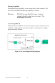
Emergency Input
If an emergency stop occurs (value is 1), pulse outputs will be disabled,
voltage output values become 0 V and PCI-1241/42’s built-in LATCH
will latch the status of the emergency stop channel.
Bouncing State
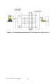
When the mechanical switch in Figure 3-9 is turned from ”Open” to
”Close”, the switch will generate a bouncing state. At this time the read-
ing value will oscillate between 0 and 1. When bounce ends, the switch
conducts and the status becomes ACTIVE. On the other hand, when the
mechanical switch is turned from ”Close” to ”Open”, the bouncing state
lasts only for a short while