
User manual


PCI-1241/1242 User Manual 26
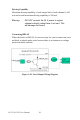
Figure 3.7: Pulse Output Format
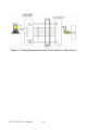
Wiring Considerations
The following is the wiring considerations, and Figure 3-8 shows the wir-
ing diagram between PCI-1241/42 and the pulse-type servo motor driver
and stepping motor driver.
• The four pulse output channels of PCI-1241/42 are A*_PAP, A*_PAN,
A*_PBP and A*_PBN. These channels are pulse command outputs for
connecting with P+, P+/, P- and P-/ channels of the pulse-type servo
motor driver / stepping motor driver accordingly, as shown in Figure 3-
8.
• Be noted that PCI-1241/42 ground channel GND must be connected to
the ground pin of the motor driver.
• It’s recommended to use twisted wires with shielding mesh for signal
transmission.