PCI-1241 4-Axis Voltage-type Servo Motor Control Card PCI-1242 4-Axis Pulse-type Servo motor Control Card User Manual
Copyright This documentation and the software included with this product are copyrighted 2007 by Advantech Co., Ltd. All rights are reserved. Advantech Co., Ltd. reserves the right to make improvements in the products described in this manual at any time without notice. No part of this manual may be reproduced, copied, translated or transmitted in any form or by any means without the prior written permission of Advantech Co., Ltd. Information provided in this manual is intended to be accurate and reliable.
2 Year Product Warranty Advantech warrants to you, the original purchaser, that each of its products will be free from defects in materials and workmanship for two years from the date of purchase. This warranty does not apply to any products which have been repaired or altered by persons other than repair personnel authorized by Advantech, or which have been subject to misuse, abuse, accident or improper installation.
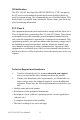
CE Notification The PCI-1241/42, developed by ADVANTECH CO., LTD., has passed the CE test for environmental specifications when shielded cables are used for external wiring. We recommend the use of shielded cables. This kind of cable is available from Advantech. Please contact your local supplier for ordering information. FCC Class A This equipment has been tested and found to comply with the limits for a Class A digital device, pursuant to Part 15 of the FCC Rules.
Packing List Before setting up the system, check that the items listed below are included and in good condition. If any item does not accord with the table, please contact your dealer immediately.
PCI-1241/1242 User Manual vi
Contents Chapter Chapter 1 Introduction ..................................................... 2 1.1 1.2 1.3 1.4 Introduction ...................................................................... Features ............................................................................ Applications ..................................................................... How to Get Started........................................................... 1.5 1.6 Software Programming Choices............................
Motor Driver 24 3.3 Pulse Output Connection................................................ 25 3.4 Local Input Connection.................................................. 27 3.5 Local Output Connection ............................................... 29 3.6 Local I/O Wiring Example............................................. 31 Figure 3.6:Differential Signal Transmission Method .. 25 Figure 3.7:Pulse Output Format ................................... 26 Figure 3.
4.6.1 4.6.2 4.6.3 Chapter Motion Command ........................................................ 51 Figure 4.11:Point-to-Point Motion Configuration Window 51 Figure 4.12:Line Command Configuration Window ... 51 Figure 4.13:2D Circle Motion Configuration Window 52 Figure 4.14:2D Circle with Line Motion Configuration Window 52 Figure 4.15:3D Arc Motion Configuration Window ... 52 Figure 4.16:2D Arc Motion Configuration Window ... 53 Figure 4.17:3D Arc with Line motion Configuration Window 53 Jog .........
C.2 Home Mode0 ......... 79 C.3 Home Mode1.................................................................. 80 C.4 Home Mode2.................................................................. 81 C.5 Home Mode3.................................................................. 82 C.6 Home Mode4.................................................................. 83 C.7 Home Mode5.................................................................. 84 C.8 Home Mode6....................................
CHAPTER 1 2 General Information This chapter provides general information on the PCI-1241/42.
Chapter 1 Introduction 1.1 Introduction PCI-1242 is a 4-Axis Pulse-type Motion Control Card and PCI-1241 is a 4-axis Pulse/Voltage-command Motion Control Card. In pulse output control, these motion control cards use a synchronous DDA (Digital Differential Analyzer) pulse generator to send out pulses evenly and simultaneously, which successfully realizes synchronous four-axis positioning and motion control.
1.2 Features PCI-1241/1242 provides the motor control functions as seen below: • Independent 4-axis motion control • Each axis of PCI-1241 can be configured independently as closed loop control (voltage command) or open loop control (pulse command). • 2/3-axis linear interpolation function • 2/3-axis circular interpolation function • Continuous interpolation function • Multiple group function.
1.3 Applications • Precise X-Y-Z position control • Precise rotation control • Packaging and assembly equipment • Machine control with up to 4 axes • Semiconductor pick and place and testing equipment • Other stepping motor and pulse/velocity-type servo motor applications 1.
Install Driver from CD-ROM, then power off PC Install Hardware and power on PC Use PCI-1241_42_61 Utility to configure hardware Use PCI-1241_42_61 Utility to test hardware Read Examples & Hardware/Software manual Start to write your own application Figure 1.
1.5 Software Programming Choices Advantech offers complete DLL drivers and utility support to help fully exploit the functions of your PCI-1241/1242. • Driver Software: Advantech PCI-1241/1242 DLL drivers (Included in the companion CD-ROM) • Motion Utility: Advantech PCI-1241_42_61 Utility (Included in the companion CD-ROM) 1.6 Accessories Advantech offers a complete set of accessory products to support the PCI1241/1242 cards. These accessories include: 1.6.
CHAPTER 2 2 Installation This chapter provides information on the installation of PCI-1241/42.
Chapter 2 Installation 2.1 Software Installation We recommend you to install the driver before you install the PCI-1241/ 42 card into your system, since this will guarantee a smooth installation process. The 32-bit DLL driver Setup program for the card is included on the companion CD-ROM that is shipped with your DAS card package. Please follow the steps below to install the driver software: Step 1: Insert the companion CD-ROM into your CD-ROM drive.
Step 3: After the installation completed, you will find PCI-1241/1242/ 1261 Card Index Manager, User Manual and Utility under the following default path: Start\Programs\Advantech Automation\Motion\PCI1241_42_61 The example source codes can be found under the corresponding installation folder such as the default installation path: C:\Program Files\Advantech\Motion\PCI-1241_42_61\Examples 2.
2.2.1 Board Layout and Jumper/Switch Settings Figure 2.2 shows the names and locations of jumpers and VRs on the PCI-1241/1242. There are 5 jumpers and 4 VRs on PCI-1241/1242. Table 2-1 shows jumpers and VRs functionalities.. Figure 2.
Table 2.1: Summary of Jumper and Connector Settings Jumpers No.
Table 2.1: Summary of Jumper and Connector Settings JP6 Set Local Input channels as source type. Onboard Common Input of Local Input Channel connects to VEX pin. (Default) Setting) Set Local Input channels as sink type. Onboard Common Input of Local Input Channel connects to VEX_GND pin.
CHAPTER 3 2 Signal Connections This chapter provides useful information about how to connect input and output signals to the PCI-1241/1242 via the I/O connector.
Chapter 3 Signal Connections Maintaining signal connections is one of the most important factors in ensuring that your application system is sending and receiving data correctly. A good signal connection can avoid unnecessary and costly damage to your PC and other hardware devices. 3.1 I/O Connector Pin Assignments There are four I/O connectors on the PCI-1241/1242. J1 is internal onboard 10-pin simple horn connector for remote I/O module PCLD-8241. J2 is also for PCLD-8241 and provided by PCI-1241 only.
Table 3.1: PCI-1241/1242 I/O J1 Conn. Signal Description – Remote I/O Pin Signal No. Name Reference Direction Description 6 RIO1_CLKP - Output RI/O Ch. 1 Clock Output + 1 RIO1_CLKN - Output RI/O Ch. 1 Clock Output - 7 RIO1_SCSP - Output RI/O Ch. 1 Slave Module Activation Signal + 2 RIO1_SCSN - Output RI/O Ch. 1 Slave Module Activation Signal - 8 RIO1_SDIP - Input RI/O Ch. 1 Data Input + 3 RIO1_SDIN - Input RI/O Ch. 1 Data Input - 9 RIO1_SDOP - Output RI/O Ch.
Table 3.2: PCI-1241/1242 I/O J2 Conn.
Table 3.3: PCI-1241/1242 I/O J3 Conn. Signal Description – MPG Input Pin Signal No.
A3_PBN 68 A3_PBP 67 34 A2_PBN 33 A2_PBP A3_PAN 66 32 A2_PAN A3_PAP 65 31 A2_PAP A1_PBN 64 30 A0_PBN A1_PBP 63 29 A0_PBP A1_PAN 62 28 A0_PAN A1_PAP 61 27 A0_PAP A3_ECZN 60 26 A2_ECZN A3_ECZP 59 25 A2_ECZP A3_ECBN 58 24 A2_ECBN A3_ECBP 57 23 A2_ECBP A3_ECAN 56 22 A2_ECAN A3_ECAP 55 21 A2_ECAP A1_ECZN 54 20 A0_ECZN A1_ECZP 53 19 A0_ECZP A1_ECBN 52 18 A0_ECBN A1_ECBP 51 17 A0_ECBP A1_ECAN 50 16 A0_ECAN A1_ECAP 49 15 A0_ECAP A3_SERVON 48 14 A2_SERVON
Table 3.4: PCI-1241/1242 I/O Conn. Signal Desc. – DDA Pulse Output Pin Signal No.
Table 3.5: PCI-1241/1242 I/O Conn. Signal Desc. – Encoder Input Pin Signal No.
Table 3.6: PCI-1241/1242 I/O Connector Signal Description – Local I/O Pin Signal Name No.
Table 3.7: PCI-1241 I/O Conn. Signal Desc. – Voltage Output & Others Pin No. Signal Name Reference Direction Description 36 A0_VO GND Output Axis 0 Voltage Output 3 A1_VO GND Output Axis 1 Voltage Output 37 A2_VO GND Output Axis 2 Voltage Output 4 A3_VO GND Output Axis 3 Voltage Output 38 VO_VCC GND Output +5V Output (500mA max.
3.2 Voltage Output Connection (PCI-1241 only) PCI-1241 supports 4-axis voltage output channels for servo driver control. PCI-1241 provides proportional-type close loop control mode, and each axis can be configured as close loop control mode or not independently. 3.2.1 Voltage Output Specifications • Resolution: 16 bits • Power on value: 0V • External load: must be over 2K • Output range: ±10V maximum 3.2.
Figure 3.
3.3 Pulse Output Connection PCI-1241/1242 supports 4-axis pulse output channels for pulse-type servo motor driver and stepping motor driver control. Pulse Output Specifications • Differential signal transmission method. Refer to Figure 3-6. A transmitter will convert the input signal X into X and X/ before outputting, and a receiver will compare the X and X/ inputs to obtain Y. Its truth table is shown in Figure 3-7.
Figure 3.7: Pulse Output Format Wiring Considerations The following is the wiring considerations, and Figure 3-8 shows the wiring diagram between PCI-1241/42 and the pulse-type servo motor driver and stepping motor driver. • The four pulse output channels of PCI-1241/42 are A*_PAP, A*_PAN, A*_PBP and A*_PBN. These channels are pulse command outputs for connecting with P+, P+/, P- and P-/ channels of the pulse-type servo motor driver / stepping motor driver accordingly, as shown in Figure 38.
Figure 3.8: Wiring Diagram Between PCI-1241/42 and Pulse-Type Driver 3.4 Local Input Connection PCI-1241/42 provides 13 dedicated input channels. There are four types of local input channels: • 4-channel Positive-direction Limit Switch Inputs – A0_LMT+, A1_LMT+, A2_LMT+, and A3_LMT+. • 4-channel Negative-direction Limit Switch Signal – A0_LMT-, A1_LMT-, A2_LMT-, and A3_LMT-. • 4-channel Home Sensor Inputs – A0_HOME, A1_HOME, A2_HOME, and A3_HOME.
Local Input Specifications • Active (Logic 0 in real hardware signal) when input voltage is between 18 V and 30 V • Inactive (Logic 1 in real hardware signal) when input voltage is between 0 V and 1 V • 2500 VDC isolation protection • The response time of the circuitry is 3 µsec because of the delay of photo coupling and the RC filter.
. Figure 3.9: Local Input Wiring Diagram 3.5 Local Output Connection PCI-1241/42 provides 5 dedicated output channels, and Figure 3-10 shows wiring diagram of local output channels. There are two types of local output channels: • 4-channel Servo On Outputs – A0_SERVON, A1_SERVON, A2_SERVON, and A3_SERVON. • 1-channel Position Ready Output – P_RDY. Local Output Specifications • Output voltage: Open collector 5 ~ 40 VDC • Sink current: 100mA max. / channel; 500mA max.
Driving Capability Maximum driving capability of each output load of each channel is 100 mA and overall maximum driving capability is 500 mA. Warning: DO NOT connect the 24 V power to output channels directly when there is no load. This will damage the board! Connecting RELAY When the load is a RELAY, it’s not necessary for you to connect an external diode to absorb pulse noise because there is an instant over voltage protection diode onboard. Figure 3.
3.6 Local I/O Wiring Example In this section, it shows a local I/O wiring example of PCI-1241/42 that helps you to setup a system quickly. Figure 3-8 and Figure 3-9 show examples of PCI-1241/42 local I/O wiring diagram of axis one. In the example, all input channels are configured as source type. (Short pin 1 and pin 2 of JP6). • Please refer to A zone: When the first axis moves through the limit switch (LS_A1_LMT+), the RELAY (indicated as R_A1_LMT+) will be activated.
• G and H zones: When the servo-ON signal of the first axis (A1_SERVON) is changed from 1 to 0, the open collector output stage is conductive, allowing current to flow through it and enable driver to servo-on. (For the definition of SERVO On please refer to the SERVO MOTOR DRIVER manual). • Zone I is the 24 VDC power for wiring on-site. Beware that if more than two 24 V power sources are used they must have common ground.
• Zone J: Under normal conditions the emergency stop switch is CLOSED. Therefore, a current loop forms in the E_STOP circuit. At this time, the reading of E_STOP is 0 and the RELAY(R_E_STOP) is activated. When the E_STOP switch is pressed down, the input current loop cuts off. The signal value of E_STOP becomes 1 and PCI-1241/ 1242 will disable pulse output and make the output of DAC become 0 V. Caution: The E_STOP function is disabled when JP5 (E_STOP) is shorted. (Default: JP5 short).
. Figure 3.12: Local I/O Wiring Example of Axis One (II) 3.6.1 MPG Encoder Input Connection In PCI-1241/1242, we provide 5 encoder input channels. Four encoder input channels are for the MOTOR DRIVER connection, and the 5th encoder input channel is specially designed for the manual pulse generator (MPG) device connector. There is an on-board 10-pin simple horn male connector (J3) on PCI-1241/1242. For PCI-1241/1242, we offer accessories such as a conversion bracket with flat cable.
MPG_VCC 5 9 MPG_GND MPG_GND MPG_ECZN MPG_ECZP MPG_ECBN MPG_ECBP MPG_ECAN 6 1 MPG_ECAP Figure 3.13: MPG Encoder Input DB-9 Connector Pin Assignment Figure 3.
3.6.2 Remote I/O Connection In PCI-1241/42, we provide capability to connect to the PCLD-8241 remote I/O module. The remote I/O module PCLD-8241 is designed to save wiring. The wiring cable between PCI-1241/42 and PCLD-8241 is a DB-9 serial cable. PCI-1241/42 supports one PCLD-8241 module. PCLD-8241 has 64 channels of isolated digital inputs and 64 channels of isolated digital outputs. For PCI-1241/42, we offer a conversion bracket accessory with flat cable for remote I/O wiring.
Figure 3.
3.6.3 Field Wiring Considerations When you use the PCI-1241/42 motor control card to connect with motor drivers, noises in the environment might significantly affect the accuracy of your control if due cautions are not taken. The following measures will be helpful to reduce possible interference running signal wires between signal sources and the PCI-1241/42.
CHAPTER 4 2 Configuration Utility This chapter provides information on the configuration utility for PCI-1241 and PCI-1242.
Chapter 4 Configuration Utility The Configuration Utility is designed for easy installation, configuration, and diagnosis of PCI-1261, PCI-1242, and PCI-1241. With the configuration utility you can set mechanical parameters, electric parameters, and home modes in the parameter table. Some basic motion functions can be operated in the utility, such as line, arc, circle, jog, and home. You can also find digital input points status easily in the utility.
You can start with the operation buttons in the lower-right corner. The operation flow chart is as follows: Figure 4.2: Utility Operation Flow Chart 4.2 Select Device When users press the “Select Device” button, a new dialog box will popup. In the dialog box, all the installed PCI-1241/1242/1261 cards are listed, and you can pick one for configuration and operation. If more than one motion card is installed, you can still identify the cards via the “Card Index” and descriptions.
4.3 Set Parameters There are a total of four pages in the parameter-setting window. They are categorized as “Mechanism”, “General/PtP Motion”, “System”, and “Home”. 4.3.1 Mechanism Configuration Advantech provides a convenient tool design the moving patterns in physical units, like mm, or mm/s. Define the entire mechanical factor in the “Mechanism” page, and then use the physical units directly when calling the API. Figure 4.
Figure 4.5: Mechanical Parameter Definition Following are introductions of each parameter: Axis: Defines which axis the parameters will affect. Max. Speed: The maximum moving speed of the object driven by the motor. For example, if the motor is driving a table, you can define the maximum speed here for safety considerations. And the DLL driver will check every output command to make sure the table does not exceed this speed.
Software Limit: Besides the hardware limitation switch, PCI-1241/42 also provides a software limit as the secondary safety factor. If the software limit was reached the motion card will stop outputting commands. Encoder: There are three types of encoders that can be defined here. They are A/B phase type, CW/CCW type, and Pulse/Direction type. Also if the pulse phase was inversed you could also define that here. Driver: The motor driver’s specifications can be input here.
4.3.2 General/PtP Motion Configuration In this page, you can define the motion characteristics for point-to-point movement. Unit: The applied length unit. It can be in millimeters (mm) or inches. Coordination Mode: The type of coordinate system is set here. It can be a relative coordinate or absolute coordinate system. Acceleration Curve and Time: The acceleration curve can be T Pattern or S Pattern. For a detailed explanation of acceleration patterns, please refer to the software manual’s chapter 2.
Figure 4.6: General/PtP Configuration Page 4.3.3 System Configuration Some important system parameters are defined in this page. Interpolation Time: Since a software driver calculates the interpolation of PCI-1241/42, the interpolation time defines how often the motion card will raise interpolation requests to the CPU of the system. If users set the interpolation time to be smaller, the velocity profile will be smoother. However, that will also consume more CPU resources.
Figure 4.7: System Configuration Page 4.3.4 Home Configuration In this page, you can set every detailed parameter related to the home function. With well-defined parameters, moving objects can reach their home precisely when requested. Home mode: PCI-1241/42 provides different home modes to fulfill different needs. There are overall fourteen home modes, from mode0 to mode13. Please refer to appendix C for further details. Sensor mode: Here the electrical types of home sensors are defined.
Home Mode Diagram: This diagram clearly shows the velocity profile, the return, slow down, and stop point in each mode. Let’s take Home mode0 as an example. In Home mode0, the motor will start at low speed FL, accelerate to high speed FH as it goes towards the home sensor. Once the home sensor has been reached, the motor will decelerate, and then stop when the speed is down to FL.
4.4 Initializing the Card When the ‘Initialize’ button is pressed, the utility will process the initialization commands to the PCI-1241/42. If the card is correctly plugged, the message “Card is active” will show on the top of utility, and the ‘Close card’ button will be enabled. Figure 4.9: The Card Is Now Active 4.5 Servo On This step is only if you need to work with servo motors. The servo motor can be activated when the “Servo On” button is pressed.
4.6 Operate Motor The configuration utility provides some basic operations in the main page. You can perform “Motion Command”, “Jog”, and “Home” here. In the mean time, the digital input signals are also displayed in the main page, so you can check the status of sensors if the hardware limit switch is not disabled. Figure 4.
4.6.1 Motion Command There are four types of commands that can be operated here, PtP, Line, Circle, and Arc. PtP: Point to Point, all axes can be operated together. The moving distance of each axis need to be defined, and all axes will start moving when the “Run” button is pressed, but will not necessarily arrive at the same time. As to the moving speed, it is defined as a percentage of the maximum motor rotation speed of each axis. Figure 4.
CircleXY, CircleYZ, and CircleZX: Performs two-dimensional circles. You need to define the center point and rotation direction, CW and CCW. The motor will start from its current point and the diameter will be calculated automatically. Figure 4.13: 2D Circle Motion Configuration Window CircleXY_UVW: Similar to CircleXY, only the UVW axes will perform line movement along with XY axes. The movement of all axes will start and stop at the same time. Figure 4.
ArcXY, ArcYZ, ArcZX: Similar to ArcXYZ, but only a 2D arc is performed in this command. Figure 4.16: 2D Arc Motion Configuration Window ArcXY_UVW: Performs a 2D arc where the UVW axes will perform a line movement at the same time. All axes will start and stop together. Figure 4.17: 3D Arc with Line motion Configuration Window 4.6.2 Jog In ‘Jog’ mode, you can operate each axis separately by simply pressing a button.
4.6.3 Home In the home mode, the checked axes can perform the home function according to the home mode setting in the parameter page. If you want each axis to go home in sequence, you can put 0~5 in the “Order” column. Then the system will follow the order from 0 to 5. Figure 4.19: Home Motion Configuration Window 4.7 Remote IO Page PCI-1241/42 supports powerful remote IO functions. The high-density IO modules are controlled and monitored via communication lines.
4.8 Motion Profile This is a user aid tool, in this page, users can check the position profile and velocity profile of each axis. Then they can easily clarify if the parameters were set correctly. Figure 4.
PCI-1241/1242 User Manual 56
CHAPTER 5 2 Software Startup Guide In this chapter you can get detailed information about card index configurations, and some samples of program usage.
Chapter 5 Software Startup Guide 5.1 Card Index Manager The card index manager is designed for applications that use more than one motion card in the system. Since the PCI cards support the plug & play function, the IO address is assigned by the system. If you put two cards in one system, it can be difficult to identity the cards without an additional identifier. In PCI-1241/42 a special utility called “Card Index Manager” is provided along with the software driver.
In the ‘Installed Device’ area, all installed cards will be listed. The card’s name, base address, and card index is also displayed. You can modify the card index by selecting the card, keying in the new index number in the lower-left text field, and then pressing the ‘Update’ button. Secondly, the default access mode of PCI-1241/1242/1261 is set as "Memory Mapping". If you want to use the cards in DOS mode, it has to be set as "IO mapping" here with Card Index manager.
Table 5.1: Sample Program Usage CheckHWStock Yes Yes Yes Yes For stable control performance, the amount of hardware pulse stocks must exceed 60 in motion period. This example demonstrates how to get the HW stock information with library. CheckOT Yes Yes Yes Yes Demonstrates how to enable/ disable the over-traveling protection. And check whether software over-traveling protection occurs. CtrlMotion Yes Yes Yes Yes Demonstrates utilizing hold/ continue/abort functions for motion controls.
Table 5.1: Sample Program Usage GetENCLatch Yes Yes Yes Yes Demonstrates how to latch a encoder value in defined conditions. GetStatus Yes Yes Yes Yes Displays current position, speed, and information of an executing motion command. GoHome Yes Yes Yes Yes Demonstrates how to use gohome functions and acquire the status of executing a gohome process. InitSys Yes Yes Yes Yes Demonstrates how to initialize a motion control system.
Table 5.1: Sample Program Usage RIOCtrl Yes Yes Yes Yes Demonstrates how to enable remote I/O functions and read/write remote I/O signals RIOError Yes Yes Yes Yes Demonstrates how to design a remote I/O ISR and enable a transmission error to trigger this ISR. RIOInput Yes Yes Yes Yes Demonstrates how to design a remote I/O ISR and enable some specific signals of remote I/O inputs to trigger this ISR. RIOStatus Yes Yes Yes Yes Checks transmission statuses of master and slave cards.
APPENDIX A 2 Specifications This chapter provides information on the specifications of PCI-1241/42.
Appendix A Specifications A.1 Axis: Number of Axis 4 Axes 2/3-Axis Linear Interpolation 2-Axis Circular Interpolation Range -8,388,608 ~ +8,388,607 for each axis Speed 1 PPS ~ 4M PPS Precision ± 0.
A.2 Voltage Output: (PCI-1241 only) Voltage Output Resolution 16 bits Output Range -10V ~ +10V Max. Update Rate 625 KHz Relative Accuracy 1 LSB Differential Nonlinearity +- 0.001% FSR Offset < 1 LSB Slew Rate 10 V / us Driving Capability +- 5mA Output Impedance 0.1 max. External Load Must be over 2K Setting time 1.6 us (to +- 0.
A.3 Pulse Output: 1 PPS ~ 4M PPS Pulse Output Range Precision +- 0.1% Change of Acceleration for S Curve 954 ~ 31.
A.4 Encoder Input: Input Pulse for Encoder Interface Input 5 channels Encoder Pulse Input Type Quadrature (A/B phase) or Up/Down Counts per Encoder Cycle X0, x1, x2, x4 (A/B phase only) Interface Differential with Photo Coupler Max. Input Frequency 2 MHz Input Voltage Single Ended Configuration Logic High : CH- > 3V CH+ = 0V(GND) Logic Low : CH- < 0.8V CH+ = 0V(GND) CH- Max.
A.5 Local Input/Output Input Signal Positive-direction Limit Switch 4 channels Negative-direction Limit Switch Signal 4 channels Home Sensor 4 channels Emergency Stop 1 channel Max. Input Frequency 20KHz Input Voltage Low 18 VDC min. 30 VDC max. High 0 VDC min. 1 VDC max. Input Current Output Signal 1 VDC 0.5 uA (typical) 18 VDC 3.3 mA (typical) 30 VDC 5.
A.
PCI-1241/1242 User Manual 70
APPENDIX B 2 Block Diagram This chapter provides information on the block diagram for PCI-1241/1242.
Appendix B Block Diagram B.1 Appendix B. Block Diagram Figure B-1 shows PCI-1241/1242 system block diagram. Circuits of block (13), (14), (16), (17) and (18) are hardware close loop control function provided by PCI-1241 only, and PCI-1242 doesn’t support this function. Figure B.
B.2 Open Loop Motion Control (Pulse Command) PC Controller sends commands to the PCI BUS interface circuit (4) on PCI-1241/1242 card through PCI BUS (1). At this time, the command and state register (5) with system control circuit (8) will decode commands and enable DDA generator (9) in the driver to send out pulses evenly (selectable to A/B PHASE, CW/CCW, and PULSE/DIRECTION formats).
B.3 Close Loop Motion Control (Velocity Command) The PC Controller sends commands to the PCI BUS interface circuit (4) on the PCI-1241/1242 card through PCI BUS (1). At this time, the command and state register (5) with system control circuit (8) will decode commands and enable DDA generator (9) in the driver to send out pulses evenly (selectable to A/B PHASE, CW/CCW, and the PC Controller sends commands to the PCI BUS interface circuit (4) on the PCI-1241 card through PCI BUS (1).
Figure B.3: P-type Control Method in Close Loop Control B.4 Local Input / Output The PC Controller sends commands to the ASIC on PCI-1241/1242 through the PCI BUS. This ASIC will read or write information to local I/ O (21) based on instructions. The outputs through photo coupling isolation (22) are amplified by a Darlington output stage. Inputs are also entered to local IO (21) through photo coupling isolation (21). Besides, Local I/O can be operated by the CPU independently from other functions. B.
PCI-1241/1242 User Manual 76
C APPENDIX 2 Home Function An accurate home position is fundamental for every precision machine. In order to manage the various requirements for the home position, PCI-1241 and PCI-1242 each provide a total of 14 home modes. This chapter gives users an overview of each home mode and its characteristics. After reading this chapter, it should be easier to choose the most suitable home mode for your application.
Appendix C Home Function C.1 How to Read the Home Velocity Profile Since the homing process is quite complex, PCI-1241/1242/1261 provides a ‘Home Pattern Graph’ for each mode to give users a clear concept about how the home function proceeds. In the Home velocity profile, there are three types of sensor inputs that can be found, and they are all high-active. “HOME” represents the status of the home sensor, and the raising edge means the home sensor was triggered.
C.2 Home Mode0 In Home mode0, the motor will start up at low speed FL, and accelerate to high speed FH towards the home sensor. Once the home sensor is reached, the motor will decelerate. And then stop when the speed is down to FL. If the home sensor was active at start up, or the limit switch was met first, the motor will go in the opposite direction when reaching the limit switch. Then it will keep moving until it crosses the home sensor, and finally search the home signal again.
C.3 Home Mode1 In Home Mode1, the motor will start up at speed FL, and accelerate to speed FH towards the home sensor. Once the home sensor is reached, the motor will decelerate. The main difference with mode0 is that in this mode, the motor will go back and approach the home again with low speed FL. This makes the stop point even closer to the raising edge of the home sensor.
C.4 Home Mode2 In Home mode2, the motor will start up at low speed FL, and accelerate to high speed FH towards the home sensor. Once the home sensor is reached, the motor will decelerate, and search for an encoder index signal with FL. Meanwhile, you can configure how many index counts will be ignored with “EIC”. When EIC is ‘1’, this means one index will be ignored and the motor will stop at the second index after the home sensor is triggered. Like case 1 in the following diagram.
C.5 Home Mode3 In Home mode3, the motor will start up at low speed FL, and accelerate to high speed FH towards the home sensor. Once the home sensor is reached, the motor starts to search for an encoder index signal with high speed FH. After the index is reached, the motor will decelerate to FL then stop. Meanwhile, you can configure how many index counts will be ignored with parameter “EIC”.
C.6 Home Mode4 In Home mode4, the motor will start up at low speed FL, and accelerate to high speed FH towards the home sensor. Once the home sensor is reached, the motor will decelerate, and go backward while the velocity reaches FL. After changing direction, the motor will search for the index signal then stop. Meanwhile you can configure how many index counts will be ignored before stopping with parameter “EIC”.
C.7 Home Mode5 In Home mode5, the motor will start up at low speed FL, and accelerate to high speed FH towards the home sensor. Once the home sensor is reached, the motor will decelerate, and go backwards while the velocity reaches FL. After changing direction, the motor will accelerate to FH and search for the index signal, then slow down and stop. Meanwhile, you can configure how many index counts will be ignored before stopping with parameter “EIC”.
C.8 Home Mode6 In Home mode6, the motor will start up at low speed FL, and accelerate to high speed FH towards the limit switch. Once the limit switch is reached, the motor will stop immediately. LMT Case 1 Figure C.7: Velocity Profile of Home Mode6 C.9 Home Mode7 In Home mode7, the motor will start up at low speed FL, and accelerate to high speed FH towards the limit switch. Once the limit switch is reached, the motor will stop, and then go backwards at speed FL.
C.10 Home Mode8 In Home mode8, the motor will start up at low speed FL, and accelerate to high speed FH towards the limit switch. Once the limit switch is reached, the motor will stop, and go backwards at speed FH. After changing direction, the motor will decelerate to FL then stop when the index signal condition was met. Meanwhile, you can configure how many index counts will be ignored before stopping with parameter “EIC”.
C.11 Home Mode9 In Home mode9, the motor will start up at speed FL, and accelerate to speed FH towards the home sensor. Once the home sensor is reached, the motor will decelerate and go backward at speed FL. Once the motor leave the triggered area of home sensor, it will stop immediately. If the home sensor was active at start up, or the limit switch was met first, the motor will go in the opposite direction when reaching the limit switch.
C.12 Home Mode10 In Home mode10, the motor will start up at low speed FL, and accelerate to high speed FH towards the home sensor. Once the home sensor is reached, the motor will start to search the encoder index signal for the high speed FH. After the index is reached, the motor will decelerate to FL then go backward with speed FL. At this time, the motor will stop when the index trigger edge was met.
C.13 Home Mode11 In Home mode11, the motor will start up at low speed FL, and then accelerate to high speed FH towards the home sensor. Once the home sensor is reached, the motor will decelerate, and go backward while the velocity goes down to FL. After changing direction, the motor will accelerate to FH and search for the index signal. When meeting the raising edge of index, the motor will slow down, return and approach the trigger edge again with speed FL.
C.14 Home Mode12 In Home mode12, the motor will start up at low speed FL, and then accelerate to high speed FH towards the limit switch. Once the limit switch is reached, the motor will go backwards. After changing direction, the motor will accelerate to FH and search for the index signal. When meeting the raising edge of the index, the motor will slow down, return and approach the trigger edge again at speed FL.
APPENDIX D 2 Remote I/O This chapter provides information on the remote I/O function of PCI-1241/42 and the PCLD-8241 I/O Module.
Appendix D Remote I/O Both PCI-1241 and PCI-1242 support a powerful remote IO function that dramatically save wiring by transferring the DIO command to serial communication. The PCLD-8241 is a remote IO module that can work with PCI-1241, 1242 and 1261 without extra configuration. You simply connect the PCLD-8241 and PCI-1241/42 with a 9-pin cable, and they can operate remote IO points with motion commands. D.
D.2 Specifications • Size: 107 x 290 mm • Din rail package--- TS32 (A)/TS35 (A) • 5EHDBV terminals (DINKLE) • Ambient Temperature: 0 ~ 55° C • 64 Source-Type or Sink-Type input points (Figure D.1) Figure D.
• Load current: 400mA • Off-state leakage current: 1uA Max. • Turn-ON time: 2ms Max. • Turn-OFF time: 0.2 ms Max. • Arc-Free with no snubbing circuits • Isolation: 1500Vrms • Power requirements: E5V: DC+5V (4.8V~5.5V) ---500 mA Note: If the voltage of E5V is less than +4.8 V, the PCLD-8241 will not work properly. Please refer to following table for the effective Remote IO distance.