
User manual


Table Of Contents
- PCA-6011
- Contents
- 1 Hardware Configuration
- 1.1 Introduction
- 1.2 Features
- 1.3 Specifications
- 1.4 Jumpers and Connectors
- 1.5 Board Layout: Jumper and Connector Locations
- 1.6 PCA-6011 Block Diagram
- 1.7 Safety Precautions
- 1.8 Jumper Settings
- 1.9 System Memory
- 1.10 Memory Installation Procedures
- 1.11 Cache Memory
- 1.12 Processor Installation
- 1.13 Power Model Setting and Installation
- 1.14 ATX Mode
- 2 Connecting Peripherals
- 2.1 Introduction
- 2.2 IDE Connectors (IDE1)
- 2.3 Floppy Drive Connector (FDD1)
- 2.4 Parallel Port (LPT1)
- 2.5 VGA Connector (VGA1)
- 2.6 Serial Ports (COM1, COM2)
- 2.7 PS/2 Keyboard and Mouse Connector (KBMS1)
- 2.8 External Keyboard & Mouse (KBMS2)
- 2.9 CPU Fan Connector (CPUFAN1)
- 2.10 Front Panel Connectors (JFP1, JFP2, JFP3)
- 2.11 H/W Monitor Alarm (JOBS1)
- 2.12 LAN RJ45 connector (LAN1/LAN2)
- 2.13 HD Link connector (HDAUD1)
- 2.14 Serial ATA2 Interface (SATA1 ~ SATA4)
- 2.15 LAN LED connector (LAN LED1)
- 2.16 USB (USB12, USB34, USB56, USB78)
- 2.17 Case open (JCASE1)
- 3 AMI BIOS Setup
- 3.1 Introduction
- 3.2 Entering Setup
- 3.2.1 Main Setup
- 3.2.2 Advanced BIOS Features Setup
- 3.2.3 PCI/PNP Setup
- 3.2.4 Boot Settings
- 3.2.5 Security Settings
- 3.2.6 Advanced Chipset Settings
- 3.2.7 Exit Options
- 4 Chipset Software Installation Utility
- 5 VGA Setup
- 6 LAN Configuration
- A Programming the Watchdog Timer
- B I/O Pin Assignments
- B.1 IDE Hard Drive Connector (IDE1)
- B.2 Floppy Drive Connector (FDD1)
- B.3 Parallel Port Connector (LPT1)
- B.4 VGA Connector (VGA1)
- B.5 RS-232 Serial Port (COM1, COM2)
- B.6 PS/2 Keyboard/Mouse Connector (KBMS1)
- B.7 External Keyboard Connector (KBMS2)
- B.8 CPU Fan Power Connector (CPUFAN1)
- B.9 Power LED and Keyboard Lock Connector (JFP3 / PWR_LED & KEY LOCK)
- B.10 External Speaker Connector (JFP2 / SPEAKER)
- B.11 Reset Connector (JFP1 / RESET)
- B.12 HDD LED (JFP2 / HDDLED)
- B.13 ATX Soft Power Switch (JFP1 / PWR_SW)
- B.14 SM Bus Connector (JFP2/SNMP)
- B.15 HD Link connector (HDAUD1)
- B.16 LAN LED Connector (LAN LED1)
- B.17 AT Power Connector (ATXF1)
- B.18 H/W Monitor Alarm (JOBS1)
- B.19 USB Connector (USB12, USB34, USB56, USB78)
- B.20 Case Open Connector (JCASE1)
- B.21 GPIO Pin Header (GPIO1)
- B.22 System I/O Ports
- B.23 DMA Channel Assignments
- B.24 Interrupt Assignments
- B.25 1st MB Memory Map
- B.26 PCI Bus Map
PCA-6011 User Manual 24
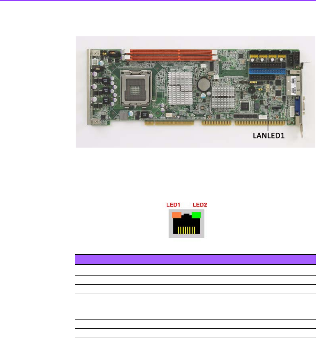
2.15 LAN LED connector (LAN LED1)
PCA-6011 provides an external LAN LED Pin header for connecting to the front side
of the chassis. With this convenient design users can easily see whether the LAN
port is active or not. Refer to Appendix B for detailed information on the pin assign-
ments.
Table 2.3: Front Panel LAN indicator connector
LAN Mode LED1 LED2
1000Mbps Link On Green On On
1000Mbps Active Green on Green Flashes
1000Mbps Link Off Off Off
100Mbps Link On Orange On Green On
100Mbps Active Orange On Green Flashes
100Mbps Link Off Off Off
10Mbps Link On Off Green On
10Mbps Active Off Green Flashes
10Mbps Link Off Off Off