
User`s manual

18 PCA-6740 User's Manual
2.9 Flat panel display connector (CN4)
CN4 consists of a 44-pin, dual-in-line header.
The power supply (+12 V) for CN4 is dependant on the supply
connected to the board. Therefore make sure that CN17 is connected
to a +12 V power supply.
The PCA-6740 provides a bias control signal on CN4 which can be
used to control the LCD bias voltage. It is recommended that the LCD
bias voltage not be applied to the panel until the logic supply voltage
(+5 V or +3.3 V) and panel video signals are stable. Under normal
operation the control signal (ENAVEE) is active high. When the PCA-
6740 board's power is applied, the control signal is low until just after
the relevant flat panel signals are present.
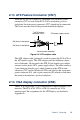
2.10 ATX power button (CN6, pins 17,19)
The PCA-6740 provides an ATX power input connector. When
connected with the ATX power switch, the ATX power switch connec-
tor (CN6) enables power On/Off from the chassis.
2.11 Reset switch (CN6, pins 9,11)
If you install a reset switch, it should be a single pole switch rated at
10 mA, 5 V. Momentarily pressing the switch will activate a reset.
For reset switch pin assignments, please see Appendix A.
2.12 IR connector (CN6 pins 12,14,16,18,20)
This connector supports the optional wireless infrared transmitting and
receiving module. This module mounts on the system case. You must
configure the setting through BIOS setup.