
User`s manual

16 PCA-6740 User's Manual
The following sections tell how to make each connection. In most
cases, you will simply need to connect a standard cable. All of the
connector pin assignments are shown in Appendix A.
Warning! Always completely disconnect the power cord from
your chassis whenever you are working on it. Do not
make connections while the power is on. Sensitive
electronic components can be damaged by a
sudden rush of power. Only experienced electronics
personnel should open the PC chassis.
Caution! Always ground yourself to remove any static charge
before touching the CPU card. Modern electronic
devices are very sensitive to static electric charges.
Use a grounding wrist strap at all times. Place all
electronic components on a static-dissipative
surface or in a static-shielded bag when they are not
in the chassis.
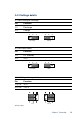
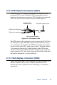
2.6 Enhanced IDE connector (CN1)
You can attach two IDE (Integrated Device Electronics) drives to the
PCA-6740 internal controller. The PCA-6740 CPU card has an EIDE
connector, CN1.
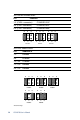
Wire number 1 on the cable is red or blue, and the other wires are gray.
Connect one end to connector CN1 on the CPU card. Make sure that
the red (or blue) wire corresponds to pin 1 on the connector. See
Figure 2-1, where pin 1 is indicated with a triangle and a solid square.
Unlike floppy drives, IDE hard drives can connect in either position on
the cable. If you install two drives, you will need to set one as the
master and one as the slave. You do this by setting the jumpers on the
drives. If you use just one drive, you should set it as the master. See
the documentation that came with your drive for more information.
Connect the first hard drive to the other end of the cable. Wire 1 on the
cable should also connect to pin 1 on the hard drive connector, which
should be labeled on the drive circuit board. Check the documentation
that came with the drive for more information. If you are using a
second drive, connect it to the remaining connector on the same cable.