PCA-6740 ISA STPC Elite 133 Half-size CPU card with CPU/32MB SDRAM/VGA/LCD/ LAN/DOC/CF/PC104 User’s Manual
Copyright notice This document is copyrighted 2002, by Advantech Co., Ltd. All rights are reserved. The original manufacturer reserves the right to make improvements to the products described in this manual at any time without notice. No part of this manual may be reproduced, copied, translated or transmitted in any form or by any means without the prior written permission of the original manufacturer. Information provided in this manual is intended to be accurate and reliable.
Packing list Before installing your board, ensure that the following materials have been received: • 1 PCA-6740 Series all-in-one single board computer • 1 Startup Manual (part no. 2006674000) • 1 utility disk / CD including utilities and manual (in PDF format) • 1 hard disk drive (IDE) interface cable (40-pin) (part no. 1701400601) • 1 keyboard / PS/2 mouse cable (part no. 1700060202) • 1 COM port / parallel port cable (part no. 1701260303) • 1 floppy disk drive interface cable 700 mm (28") (part no.
Contents Chapter 1 General Information ............................................ 1 1.1 Introduction ....................................................................................... 2 1.2 Features ............................................................................................ 3 1.3 Specifications .................................................................................... 4 1.4 Board layout and dimensions ............................................................
Chapter 3 Award BIOS Setup ............................................. 23 3.1 System test and initialization .......................................................... 24 3.2 Award BIOS setup ....................................................................... 25 3.2.1 Entering setup ..................................................................... 25 3.2.2 Standard CMOS Features Setup ......................................... 26 3.2.3 Advanced BIOS Features Setup ..................................
Chapter 6 Floppy Disk Drive Installation .......................... 77 6.1 6.2 Installation for Windows 95 ...................................................... 78 Installation for Windows 98 ....................................................... 87 Appendix A Pin Assignments.............................................. 93 IDE hard drive connector (CN1) ............................................................ 94 Floppy drive connector (CN2) ..........................................................
Figures Figure 1-1: PCA-6740 dimensions (component side) ....................................... 6 Figure 2-1: Board Layout: Connector Locations(component side) .................. 8 Figure 2-2: Locating Jumpers .......................................................................... 9 Figure 3-1: BIOS setup program initial screen ................................................ 25 Figure 3-2: Standard CMOS Features screen ..................................................
Tables Table 2-1: Jumpers ........................................................................................ 10 Table 2-2: Connectors .................................................................................... 11 Table 2-3: Serial port connections (COM1, COM2) ........................................ 21 Table 2-4: Serial port default settings ............................................................ 21 Table A-1: IDE hard drive connector ....................................................
CHAPTER 1 General Information This chapter gives background information on the PCA-6740.
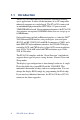
1.1 Introduction The PCA-6740 is the ultimate cost-effective solution for limitedspace applications. It offers all the functions of an AT-compatible industrial computer on a single board. The PCA-6740 comes with an embedded high-performance STPC Elite 133 processor and 32MB SDRAM on board. For maximum performance, the PCA-6740 also supports one optional SODIMM socket that can accept up to 64 MB memory.
1.
1.3 Specifications 1.3.1 Standard SBC functions • CPU: Embedded STMicroelectronics STPC Elite 133 MHz processor (provides fanless operation) • BIOS: 4 Mbit Flash BIOS, -Supports Plug & Play, APM -Supports Ethernet Boot ROM -Supports boot from CD-ROM -Supports boot from LS-120 ZIP™ Drive -Optional Customer icon can be supplied • Chipset: STPC Elite 133 • System memory: Onboard 32MB SDRAM, and one optional SDRAM SODIMM max. 64MB socket • PCI IDE interface: One Enhanced IDE interface.
1.3.2 Local-bus flat panel/VGA interface • Chipset: SMI LynxEM+ 712G • Display memory: 2MB • Display type: Simultaneous support for CRT and 18-bit TFT LCD display (supports 3.3 V and 5 V LCD) • Resolution: Non-interlaced CRT monitor resolution up to 1280 x 1024 @ 256 colors, Panel resolutions up to 1024 x 768 @ 64K colors TFT panel 1.3.3 Ethernet interface • Chipset: RTL 8139C • Ethernet interface: PCI 10/100 Mbps Ethernet. IEEE 802.
1.
CHAPTER 2 Connecting Peripherals This chapter tells how to connect peripherals, switches and indicators to the PCA-6740 board. You can access most of the connectors from the top of the board while it is installed in the chassis. If you have a number of cards installed, or your chassis is very tight, you may need to partially remove the card to make all the connections.
2.
2.
2.3 Jumpers and connectors Connectors on the board link it to external devices such as hard disk drives, a keyboard or expansion bus connectors. In addition, the board has a number of jumpers that allow you to configure your system to suit your application.
The following table lists the connectors on the PCA-6740.
2.4 Setting jumpers 2.4.1 Introduction You may configure your card to match the needs of your application by setting jumpers. A jumper is the simplest kind of electrical switch. It consists of two metal pins and a small metal clip (often protected by a plastic cover) that slides over the pins to connect them. To "close" a jumper, you connect the pins with the clip. To "open” a jumper you remove the clip. Sometimes a jumper will have three pins, labeled 1, 2, and 3.
2.4.2 Settings details J1: CMOS Charge & Discharge Pin Function 1-2 Discharge 2-3 Charge 3 2 1 3 Discharge 2 1 Charge J2: LAN Power Select Pin Function 1-2 5 V Standby 2-3 VCC* 3 2 1 3 5 V Standby 2 1 VCC* JP1: LCD High drive signal buffer power Pin Function 1-3, 2-4 +5 V* 3-5, 4-6 +3.3 V +5 V* +3.
JP2: RS-232/422/485 Select Pin Function 1-2 (CN10 connector) COM2/RS-232* 3-4 (CN11 connector) COM2/RS-422 5-6 (CN11 connector) COM2/RS-485 2 1 4 6 2 3 5 1 RS-232* 4 6 2 3 5 1 RS-422 4 6 3 5 RS-485 JP3: DOC address select Pin Address at 1-2 D4000h 3-4 DC000h 1-2, 3-4 CC000h 1-2, 5-6 D0000h 3-4, 5-6 D8000h 2 1 4 6 2 3 5 1 D4000h 2 1 6 2 3 5 1 *Default Settings 14 PCA-6740 User's Manual 6 2 3 5 1 DC000h 4 D0000h 4 6 3 5 CC000h 4 6 3
2.5 Watchdog timer action (JP4) When the watchdog timer activates (CPU processing has come to a halt), it can reset the system or generate an interrupt on IRQ11.
The following sections tell how to make each connection. In most cases, you will simply need to connect a standard cable. All of the connector pin assignments are shown in Appendix A. Warning! Always completely disconnect the power cord from your chassis whenever you are working on it. Do not make connections while the power is on. Sensitive electronic components can be damaged by a sudden rush of power. Only experienced electronics personnel should open the PC chassis.
2.7 FDD connector (CN2) You can attach up to two floppy disk drives to the PCA-6740's onboard controller. You can use any combination of 5.25" (360 KB/ 1.2 MB) and/or 3.5" (720 KB/1.44/2.88 MB) drives. The card comes with a 34-pin daisy-chain drive connector cable. On one end of the cable is a 34-pin flat-cable connector. On the other end are two sets of floppy disk drive connectors. Each set consists of a 34pin flat-cable connector (usually used for 3.
2.9 Flat panel display connector (CN4) CN4 consists of a 44-pin, dual-in-line header. The power supply (+12 V) for CN4 is dependant on the supply connected to the board. Therefore make sure that CN17 is connected to a +12 V power supply. The PCA-6740 provides a bias control signal on CN4 which can be used to control the LCD bias voltage. It is recommended that the LCD bias voltage not be applied to the panel until the logic supply voltage (+5 V or +3.3 V) and panel video signals are stable.
2.13 ATX Feature Connector (CN7) When the PCA-6740 is used as a standalone card, the main power connector (CN7) is used. If the PCA-6740 is used with a passive backplane, the main power connector (CN7) should not be connected. This is because the card will be powered from the backplane.
2.15 PC/104 connectors (CN10) The PCA-6740 is equipped with a 16-bit ISA signal PC/104 connector for future expansion. See Appendix D for details. 2.16 Ethernet connector (CN11) The PCA-6740 is equipped with a high performance 32-bit PCI-bus Fast Ethernet interface which is fully compliant with IEEE 802.3u 10/100Base-T specifications. It is supported by all major network operating systems. The medium type can be configured via the rset8139.EXE program included on the utility disk.
Table 2-3: Serial port connections (COM1, COM2) Connector Function COM1,3*,4* RS-232 COM2 RS-232/422/485 2.17.1 RS-232 connection (COM1:CN15) Different devices implement the RS-232 standard in different ways. If you are having problems with a serial device, be sure to check the pin assignments for the connector. 2.17.2 RS-232/422/485 connection (COM2: CN10: RS-232; CN11: RS-422/485) COM2 is an RS-232/422/485 serial port.
2.18 Internal keyboard connector (CN16) In addition to the PS/2 mouse/keyboard connector, an additional external keyboard connector is provided. For external keyboard pin assignments, see Appendix A. 2.19 AT power connector (CN17) If you prefer not to acquire power through the PCA-6740 backplane via the gold H-connectors, The big 4P power connector (CN17) also provides power input connectors for +5 V, and +12 V. 2.
CHAPTER 3 Award BIOS Setup This chapter describes how to set BIOS configuration data.
3.1 System test and initialization These routines test and initialize board hardware. If the routines encounter an error during the tests, you will either hear a few short beeps or see an error message on the screen. There are two kinds of errors: fatal and non-fatal. The system can usually continue the boot up sequence with non-fatal errors.
3.2 Award BIOS setup Award’s BIOS ROM has a built-in Setup program that allows users to modify the basic system configuration. This type of information is stored in battery-backed CMOS RAM so that it retains the Setup information when the power is turned off. 3.2.1 Entering setup Power on the computer and press immediately. This will allow you to enter Setup.
3.2.2 Standard CMOS Features Setup When you choose the Standard CMOS Features option from the Initial Setup screen menu, the screen shown below is displayed. This standard Setup Menu allows users to configure system components such as date, time, hard disk drive, floppy drive and display. Once a field is highlighted, on-line help information is displayed in the left bottom of the Menu screen.
3.2.3 Advanced BIOS Features Setup By choosing the Advanced BIOS Features option from the Initial Setup Screen menu, the screen below is displayed. This sample screen contains the manufacturer’s default values for the PCA-6740.
3.2.4 Advanced Chipset Features Setup By choosing the Advanced Chipset Features Setup option from the Initial Setup Screen menu, the screen below is displayed. This sample screen contains the manufacturer’s default values for the PCA-6740.
3.2.5 Integrated Peripherals Setup By choosing the Integrated Peripherals option from the Initial Setup screen menu, the screen below is displayed. This sample screen contains the manufacturer’s default values for the PCA6740. The PANEL TYPE by default supports a 18-bit 640 x 480 TFT LCD panel display.
3.2.6 Power Management Setup By choosing the Power Management Setup option from the Initial Setup Screen menu, the screen below is displayed. This sample screen contains the manufacturer’s default values for the PCA-6740.
3.2.7 PnP/PCI Configurations Setup By choosing the PnP/PCI Configurations option from the Initial Setup Screen menu, the screen below is displayed. This sample screen contains the manufacturer’s default values for the PCA6740.
3.2.8 Set Password To enable the password feature, you must first select either Setup or System under the Security Option in the Advanced BIOS Features Setup. To change the password, choose the Set Password option from the Initial Setup Screen menu and press . 1. If the CMOS is bad or this option has never been used, a default password is stored in the ROM. The screen will display the following messages: Enter Password: Press . 2.
Figure 3-8: Set Password Screen 3.2.9 Save & Exit Setup If you select this option and press , the values entered in the setup utilities will be recorded in the chipset’s CMOS memory. The microprocessor will check this every time you turn your system on and compare this to what it finds as it checks the system. This record is required for the system to operate.
3.2.10 Exit without saving Selecting this option and pressing lets you exit the Setup program without recording any new values or changing old ones.
CHAPTER 4 SVGA Setup • Introduction • Installation of SVGA driver for Windows 95/98/NT4.
4.1 Introduction The PCA-6740 has an on-board LCD/VGA interface. The specifications and features are described as follows: 4.1.1 Chipset The PCM-6740 uses a SMI LynxEM+ 712G chipset for its SVGA controller. It supports many popular 18-bit LCD displays and conventional analog CRT monitors. The VGA BIOS supports LCD. In addition, it also supports interlaced and non-interlaced analog monitors (color and monochrome VGA) in high-resolution modes while maintaining complete IBM VGA compatibility.
4.2 Installation of SVGA driver Complete the following steps to install the SVGA driver. Follow the procedures in the flow chart that apply to the operating system that you are using within your PCM-6740. Important: The following windows illustrations are examples only. You must follow the flow chart instructions and pay attention to the instructions which then appear on your screen. Note 1: The CD-ROM drive is designated as "D:" throughout this chapter.
4.2.1 Installation for Windows 95 1. In the Windows 95 Main screen, click on "Start," select "Settings," then "Control Panel." Double click the "Display" icon.
2. Select the "Settings" tab, then click the "Advanced Properties" button.
3. Click the "Change" button, then "Have Disk ..." to change the default VGA driver. 4. Direct the path to the SMI VGA driver on the CD, and click "OK.
5. Select "Yes" to reboot the system.
4.2.2 Installation for Windows 98 1. Insert the disk into the CD-ROM drive. 2. Click on the "Start" icon, then select "Settings," "Control Panel," and double click on "Display.
3. Select the "Settings" tab, then click "Advanced...
4. Click the "Adapter" tab, and then the "Change ..." button.
5. Select "Display a list of all the drivers in a specific location..." then click "Next.
6. Click the "Have Disk ..." button 7. Direct the path to the SMI VGA driver in the CD and click "OK" to install the driver.
8. Reboot the system.
4.2.3 Installation for Windows NT 1. Click the "Start" icon, select "Settings," then "Control Panel,"and double click "Display.
2. Click the "Settings" tab, then the "Display Type..." button.
3. Click "Change...
4. Click the "Have Disk..." button.
5. a. Insert the disk into the CD-ROM drive. b. Type “D:\slotpc\6740\VGA\WINNT” (where D: represents your CD-ROM drive) in the blank. c. Press “OK”. 6. Press "Yes" to proceed.
7. Press "Yes" to restart the system. 4.3 Further information For further information about the PCI/SVGA installation in your PCA-6740, including driver updates, troubleshooting guides and FAQ lists, visit the following web resources: SMI web site: http://www.siliconmotion.com Advantech web sites: http://www.advantech.com http://www.advantech.com.
54 PCA-6740 User's Manual
CHAPTER 5 PCI Bus Ethernet Interface This chapter provides information on Ethernet configuration.
5.1 Introduction The PCA-6740 is equipped with a high performance 32-bit Ethernet chipset which is fully compliant with IEEE 802.3 100 Mbps CSMA/ CD standards. It is supported by major network operating systems. It is also both 100Base-T and 10Base-T compatible. The medium type can be configured via the RSET8139.exe program included on the utility disk. The Ethernet port provides a standard RJ-45 jack on board.
5.2.1 Installation for Windows 95 1. Click the "Start" icon, select "Settings," then "Control Panel," then "System.
2. Click "Device Manager" folder, then double click "PCI Ethernet Controller.
3. Select the "Driver" folder, then click "Update Driver ...
4. Select "No, select driver from list," and click the "NEXT" button.
5. Highlight "Network Adapters" then click the "NEXT" button.
6. Click "Have Disk ..." to update the LAN driver. 7. Direct the path to the LAN driver to install it.
8. Insert "Windows 95 CD" and click "OK." 9. Reboot the system.
5.2.2 Installation for Windows 98 1. Click "Start," then "Settings," and "Control Panel." Double click on the "System" icon.
2.
3. Click on "Properties," select the "Driver" tab, then "Update Driver...
4. Select "Display a list of all the...." then hit "NEXT.
5. Select "Network adapters," and click the "NEXT" button.
6. Click the "Have Disk..." button.
7. a. Insert the CD ROM. b. Type “D:\LAN\WIN98_V3.94” (where D: represents your CDROM drive). c. Click “OK”. 8. The system will now install the driver.
9. Insert the Windows 98 CD in the CDROM drive. 10. Reboot the system.
5.2.3 Installation for Windows NT 1. a. Select “Start,” “Settings,” and “Control Panel.” b. Double click “Network”.
2. Click on "Select from list.
3. Click "Have Disk..." 4. Type in the path, then click "OK.
5. Insert the Windows NT CD. 6. Reboot.
5.3 Further information Realtek website: www.realtek.com Advantech websites:www.advantech.com www.advantech.com.
CHAPTER 6 Floppy Disk Drive Installation This chapter provides information on installation of a standard floppy drive for Windows 95 and 98.
6.1 Installation for Windows 95 1. After BIOS POST, press “Shift+F5” to interrupt the system. 2. Execute the utility file, STM95fdc.bat, which is on the accompanying CD. This will create directory C:\STM95FDC on the C drive and copy files into it. 3. Reboot the system and restart Windows 95. 4. Click the “Start” button, select “Settings,” then “Control Panel,” and double click the “System” icon.
5. In “System Properties,” click the “Device Manager” tab.
6. Select the “Standard Floppy Disk Controller” listing, and remove it. Do not reboot the system.
7. Click “Start,” “Settings,” “Control Panel,” and “Add New Hardware.
8. Click the “Yes (Recommended)” button. The system will detect the new hardware.
9. Highlight “Floppy Disk Controllers,” and click the “NEXT” button.
10. Click “Have Disk …” 11. Type in the path of the driver.
12. Click “Finish” and reboot the system.
13. In the “Device Manager,” remove any instance of “STMicroelectronics Floppy Disk Controller” that is marked with a red X. Note : If the standard FDD is not updated as specified above, the system might hang up during a FDD read/write operation.
6.2 Installation for Windows 98 1.
2. In “System Properties,” click “Device Manager” and select the “Standard Floppy Disk Controller” listing.
3. Click “Properties,” and select “Driver.
4. Click “Display a list of all the drivers…,” and then “NEXT.
5. Click the “Have Disk …” button.
6. Type in the path of the STM floppy controller, then hit "OK." 7. Reboot the system.
APPENDIX A Pin Assignments This appendix contains information of a detailed or specialized nature.
IDE hard drive connector (CN1) Table A-1: IDE hard drive connector Pin Signal Pin Signal 1 3 5 7 9 11 13 15 17 19 21 23 25 27 29 31 33 35 37 2 4 6 8 10 12 14 16 18 20 22 24 26 28 30 32 34 36 38 39 IDE RESET* DATA 7 DATA 6 DATA 5 DATA 4 DATA 3 DATA 2 DATA 1 DATA 0 SIGNAL GND DRQ* IO WRITE* IO READ* IO CHANNEL READY ACK IRQ14 (IDE IRQ) ADDR 1 ADDR 0 HARD DISK SELECT 0 IDE ACTIVE* * low active 94 PCA-6740 User's Manual 40 GND DATA 8 DATA 9 DATA 10 DATA 11 DATA 12 DATA 13 DATA 14 DATA 15 N/C GND GND
Floppy drive connector (CN2) 33 31 3 1 34 32 4 2 Table A-2: Floppy drive connector Pin Signal Pin Signal 1 3 5 7 9 11 13 15 17 19 21 23 25 27 29 31 33 GND GND GND GND GND GND GND GND GND GND GND GND GND GND GND GND GND 2 4 6 8 10 12 14 16 18 20 22 24 26 28 30 32 34 DENSITY SELECT* N/C N/C INDEX* MOTOR 0* DRIVE SELECT 1* DRIVE SELECT 0* MOTOR 1* DIRECTION* STEP* WRITE DATA* WRITE GATE* TRACK 0* WRITE PROTECT* READ DATA* HEAD SELECT* DISK CHANGE* * low active Appendix A Pin Assignments 95
Parallel port connector (CN3) 25 23 3 1 26 24 4 2 Table A-3: Parallel port connector Pin Signal 1 2 3 4 5 6 7 8 9 10 11 12 13 14 15 16 17 18 19 20 21 22 23 24 25 26 STROBE* AUTOFD* D0 ERROR* D1 INIT* D2 SLCTINI* D3 GND D4 GND D5 GND D6 GND D7 GND ACK* GND BUSY GND PE GND SLCT GND * low active 96 PCA-6740 User's Manual
Flat panel display connector (CN4) Table A-4: Flat panel display connector Pin Function Pin Function 1 3 5 7 9 11 13 15 17 19 21 23 25 27 29 31 33 35 37 39 41 43 +12 V GND VDD ENAVEE P0 P2 P4 P6 P8 P10 P12 P14 P16 P18 P20 P22 GND SFK DE (M) GND N/C VSAFE (ENAVDD) 2 4 6 8 10 12 14 16 18 20 22 24 26 28 30 32 34 36 38 40 42 44 +12 V GND VDD GND P1 P3 P5 P7 P9 P11 P13 P15 P17 P19 P21 P23 GND FLM LP ENABKL N/C N/C Appendix A Pin Assignments 97
CN6- External speaker (pins 1,3,5,7) External speaker connector Table A-5a: External speaker connector Pin Signal 1 3 5 7 +5V N/C Internal speaker input External speaker signal CN6- Keyboard lock connector (pins 2,4) Keyboard Lock Connector Table A-5b: Keyboard lock connector 98 Pin Signal 2 4 keyboard lock GND PCA-6740 User's Manual
CN6- System reset switch conn (pins 9,11) Reset Connector Table A-5c: System reset switch connector Pin Signal 9 11 MR_RESET GND CN6- IR connector (pins 12,14,16,18,20) IR connector Table A-5d: IR connector Pin Signal 12 14 16 18 20 +5 V N/C IR_RX GND IR_TX Appendix A Pin Assignments 99
CN6- HDD LED connector (pins 13,15) HDD LED Connector Table A-5e: HDD LED connector Pin Signal 13 15 IDE LED + IDE LED - CN6- ATX power button (pins 17,19) ATX power button connector Table A-5f: ATX power button 100 Pin Signal 17 19 Power ON GND PCA-6740 User's Manual
ATX power standby connector (CN7) 1 2 3 Table A-6: ATX power standby connector Pin Signal 1 2 3 5 V SB N/C PS_ON LCD Inverter Power (CN8) 5 4 3 2 1 Table A-7: LCD Inverter connector Pin Signal 1 2 3 4 5 12V GND Backlight On/Off Control Backlight Control 5V Appendix A Pin Assignments 101
CRT Display Connector (CN9) 5 1 6 11 10 6 15 Table A-8: CRT display connector Pin Signal Pin Signal 1 2 3 4 5 6 7 8 RED GREEN BLUE N/C GND GND GND GND 9 10 11 12 13 14 15 N/C GND N/C N/C H-SYNC V-SYNC N/C COM2 RS-422/485 connector (CN13) 1 3 5 7 2 4 6 8 9 10 Table A-9: COM2 RS-232/422/485 connector 102 Pin RS-422 port RS-485 port 1 2 3 4 5 6 7 8 9 10 TXDN/C TXD+ N/C RXD+ N/C RXDN/C GND N/C DATAN/C DATA+ N/C N/C N/C N/C N/C GND N/C PCA-6740 User's Manual
COM2 RS-232 connector (CN14) 1 3 5 7 2 4 6 8 9 10 Table A-10: COM2 RS-232 connector Pin RS-232 port Pin RS-232 port 1 2 3 4 5 DCD DSR RxD RTS TxD 6 7 8 9 10 CTS DTR RI GND N/C COM1 RS-232 connector (CN15) 1 2 3 4 6 7 8 9 5 Table A-11: COM1 RS-232 connector Pin Signal 1 2 3 4 5 6 7 8 9 DCD RXD TXD DTR GND DSR RTS CTS RI Appendix A Pin Assignments 103
Internal keyboard connector (CN16) 5 4 3 2 1 Table A-12: External keyboard connector Pin Signal 1 2 3 4 5 CLK DATA NC GND +5V AT power connector (CN17) 1 2 3 4 Table A-13: AT power connector 104 Pin Signal 1 2 3 4 +12 V GND GND +5 V PCA-6740 User's Manual
Keyboard and mouse connnector (CN18) 6 5 4 3 2 1 Table A-14: Keyboard and mouse connector Pin Signal 1 2 3 4 5 6 KB DATA MS DATA GND VCC KB CLOCK MS CLOCK Appendix A Pin Assignments 105
106 PCA-6740 User's Manual
APPENDIX System Assignments • System I/O ports • DMA channel assignments • Interrupt assignments • 1st MB memory map B
B.1 System I/O ports Table B-1: System I/O ports Addr.
3C0-3CF Reserved 3D0-3DF Color/graphics monitor adapter 3F0-3F7 Diskette controller 3F8-3FF Serial port 1 443 Watchdog timer ** default setting B.2 DMA channel assignments Table B-2: DMA channel assignments Channel Function 0 Available 1 Available 2 Floppy disk (8-bit transfer) 3 Parallel** 4 Cascade for DMA controller 1 5 Available 6 Available 7 Available ** Parallel port DMA default setting: DMA 3 Parallel port DMA select: DMA 1.
B.
B.4 1st MB memory map Table B-4: 1st MB memory map Addr.
112 PCA-6740F User's Manual
APPENDIX C LCD Services This appendix contains information of a detailed or specialized nature. It includes information about 18-bit TFT LCD interfaces.
C.1 LCD services LCD screens are very popular on Advantech's CPU cards, biscuit PCs and POS series products, such as the PCA-6135/6145/6153, and PCA-6751/PCA-6751V. "Lighting" LCDs is virtually impossible without technical expertise. Advantech provides LCD lighting and integration services to assist our customers in setting up their systems.
APPENDIX D Installing PC/104 Modules This appendix gives instructions for installing PC/104 modules.
D.1 Installing PC/104 modules The PCA-6740F PC/104 connectors give you the flexibility to attach PC/104 modules. Installing these modules on the PCA-6740F is quick and simple. The following steps show how to mount the PC/104 modules: 1. Remove the PCA-6740F from your system, paying particular attention to the safety instructions already mentioned above. 2. Make any jumper or link changes required to the CPU card now. Once the PC/104 module is mounted you may have difficulty in accessing these. 3.
PC /104 M ou n tin g S u p p ort Fem a le PC A-6740 M ale P C /10 4 m o d ule Figure D-1: PC/104 module mounting diagram 8 .9 8 2.5 9 5 .9 9 0 .8 9 0.8 5 .1 5 .1 0 5 .1 0 8 5 .1 9 0 .2 Figure D-2: PC/104 module dimensions (mm) (±0.
Table D-1: PC/104 connectors (CN8) Pin Number Signal Row A Row B Signal Row C Row D 0 1 2 3 4 5 6 7 8 9 10 11 12 13 14 15 16 17 18 19 20 21 22 23 24 25 26 27 28 29 30 31 32 — IOCHCHK* SD7 SD6 SD5 SD4 SD3 SD2 SD1 SD0 IOCHRDY AEN SA19 SA18 SA17 SA16 SA15 SA14 SA13 SA12 SA11 SA10 SA9 SA8 SA7 SA6 SA5 SA4 SA3 SA2 SA1 SA0 0V — 0V RESETDRV +5 V IRQ9 -5 V DRQ2 -12 V ENDXFR* +12 V N/C SMEMW* SMEMR* IOW* IOR* DACK3* DRQ3 DACK1* DRQ1 REFRESH* SYSCLK IRQ7 IRQ6 IRQ5 IRQ4 IRQ3 DACK2* TC BALE +5 V OSC 0V 0V 0V SB
APPENDIX E Programming the Watchdog Timer The PCA-6740 is equipped with a watchdog timer that resets the CPU or generates an interrupt if processing comes to a standstill for any reason. This feature ensures system reliability in industrial standalone or unmanned environments.
E.1 Programming the watchdog timer To program the watchdog timer, you must write a program which writes I/O port address 443 (hex). The output data is a value of time interval. The value range is from 01 (hex) to 3E (hex), and the related time interval is 1 sec. to 62 sec. 120 Data Time Interval 01 1 sec. 02 2 sec. 03 3 sec. 04 4 sec. • • • • • • 3E 62 sec.
After data entry, your program must refresh the watchdog timer by rewriting the I/O port 443 (hex) while simultaneously setting it. When you want to disable the watchdog timer, your program should read I/O port 443 (hex).
122 PCA-6740 User's Manual
APPENDIX Mechanical Drawing F
F.