PCA-6359 Series Full-size Pentium® MMX 266 PCI/ISA-bus CPU card User’s Manual
Copyright notice This document is copyrighted, 2000, by Advantech Co., Ltd. All rights are reserved. The original manufacturer reserves the right to make improvements to the products described in this manual at any time without notice. No part of this manual may be reproduced, copied, translated or transmitted in any form or by any means without the prior written permission of the original manufacturer. Information provided in this manual is intended to be accurate and reliable.
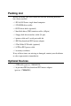
Packing List Before installing your card, make sure that the following materials have been received: • 1 PCA-6359 Series single board computer • 1 CD-ROM driver utility • 4 SCSI driver disks (optional) • 2 hard disk drive (IDE) interface cables (40-pin) • 1 floppy disk drive interface cable (34-pin) • 1 printer cable and 1 serial port cable kit • 1 PS/2 keyboard and PS/2 mouse adapter • 1 Ultra Wide SCSI cable (optional) • 1 ATX-to-PS/2 power cable • 1 warranty certificate If any of these items are missing
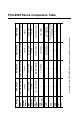
! x 2 4 ! SCSI USB EIDE 2S/1P ! 4 2 ! 4 2 Symbios SYM53C875E Ultra Wide SCSI 10/100Base-T, Intelfi 82559ER 10/100Base-T, Intelfi 82559ER x C&T 69000 256 MB SDRAM 512 KB Award, P&P 430TX Intelfi 266 MHz (MMX) PCA-6359F C&T 69000 256 MB SDRAM 512 KB Award, P&P 430TX Intelfi 266 MHz (MMX) PCA-6359VE Also refer to the PCA-6359 Series features elsewhere in this manual 2 x x x LAN C&T 69000 256 MB SDRAM 512 KB Award, P&P x 256 MB SDRAM 512 KB Award, P&P 430TX Intel
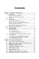
Contents Chapter 1 Hardware Configuration ...................................... 1 1.1 1.2 1.3 1.4 1.5 1.6 1.7 1.8 Introduction ................................................................................. 2 Embedded Pentium® MMX CPU ................................................. 2 Guaranteed long product supply time .......................................... 2 Features ........................................................................................ 3 Specifications .....................
2.11 External Keyboard Connector (CN12) ................................... 26 2.12 IR Connector (CN13) ................................................................ 26 2.13 Front Panel Connectors (CN16, CN17, CN18, CN19 and CN21) .................................. 27 2.13.1 Keyboard lock and power on LED (CN16) .................... 27 2.13.2 External speaker (CN17) ................................................. 27 2.13.3 Reset (CN18) ...................................................................
3.5 3.6 3.7 3.8 3.9 3.10 3.11 3.12 3.13 3.14 Chipset Features Setup ............................................................. 40 3.5.1 SDRAM (CAS Lat / RAS-to-CAS) ................................... 40 3.5.2 DRAM Speculative Read................................................... 41 3.5.3 16 Bit I/O Recovery Time / 8 Bit I/O Recovery Time ...... 41 3.5.4 Memory Hole At 15M-16M .............................................. 41 Power Management Setup .................................................
Chapter 4 PCI SVGA Setup (PCA-6359V/VE/F only) ......... 51 4.1 4.2 Introduction ............................................................................... 52 4.1.1 Chipset ............................................................................... 52 4.1.2 Display memory ................................................................. 52 4.1.3 Display types ...................................................................... 52 Installation of SVGA Driver .....................................
Appendix A Programming the Watchdog Timer .............. 83 A.1 Programming the Watchdog Timer ........................................ 84 Appendix B Pin Assignments ............................................. 87 B.1 B.2 B.3 B.4 B.5 B.6 B.7 B.8 B.9 B.10 B.11 B.12 B.13 B.14 B.15 B.16 B.17 B.18 B.19 B.20 B.21 B.22 B.23 B.24 B.25 IDE Hard Drive Connector (CN1, CN2) ................................ 88 Floppy Drive Connector (CN3) ...............................................
CHAPTER 1 Hardware Configuration This chapter gives background information on the PCA-6359 Series. It then shows you how to configure the card to match your application and prepare it for installation into your PC.
1.1 Introduction The PCA-6359 Series is a full-size CPU card designed with an on-board Intel® Pentium® MMX CPU. Featuring powerful onboard functions such as VGA, LCD, LAN, SCSI and SSD, the versatile PCA-6359 Series can meet the needs of a great many different applications. Embedded Pentium® MMX CPU The PCA-6359 Series is equipped with Intel's new embedded Pentium® Tillamook MMX 266 MHz CPU. The CPU provides high performance with low power consumption and better thermal management.
1.2 Features 1. ATX soft power switch: Through the BIOS, the power button can be defined as the "Standby" (aka "Suspend" or "Sleep") button or as the "Soft-Off" button (see Section 3.6.8 Soft-off by PWRBTN). Regardless of the setting, pushing the power button for more than 4 seconds will enter the Soft-Off mode. 2. Wake-on-modem (requires modem): This allows a computer to be turned on remotely through an internal or external modem.
5. CMOS RAM backup: When BIOS CMOS setup has been completed, data in the CMOS RAM is automatically backed up to the Flash ROM. This is particularly useful in industrial environments which may cause soft errors. Upon such an error occurring, BIOS will check the data, and automatically restore the original data for booting. 6.
1.3 Specifications Standard SBC functions • CPU: Intel® Pentium® MMX CPU 266 MHz • BIOS: Award 2 Mbit Flash BIOS, supports Plug & Play, APM 1.2, Ethernet boot ROM, and HDD/SCSI/ZIP/CD/Floppy/LS120 boot selection • Chipset: Intel® 430TX • L2 cache: 512 KB PB SRAM • System memory: Two 168-pin DIMM sockets support SDRAM memory module from 16 MB to 256 MB • PCI IDE interface: Two Enhanced IDE interfaces. Support 4 IDE devices, PIO mode 4 with bus mastering up to 16.
Ethernet controller functions (PCA-6359VE/F only) • Controller: Intel® 82559ER, 10/100 Mbps • I/O address switchless setting • Connector type: RJ-45 • Boot ROM: Built-in system (optional) SCSI function (PCA-6359F only) • Controller: Symbios SYM53C875E • PCI SCSI: Supports Ultra Wide SCSI 8-bit or 16-bit interface, up to 40 MB/s Mechanical and environmental specifications • Max. power requirement: + 5 V @ 2.
Intel® Pentium® MMX 266 CPU Intel® 430TX chipset EIDE connector 2 DIMM sockets (up to 256 MB) SYM53C875E SCSI chipset DOC® 2000 Intel® 82559ER LAN chipset Ultra Wide SCSI C&T 69000 FDD VGA chipset connector Parallel port connectors VGA connector LAN connecor COM1 1.
1.5 Safety Precautions Follow these simple precautions to protect yourself from harm and your PC from damage. 1. To avoid electric shock, always disconnect the power from your PC chassis before you work on it. Do not touch any components on the CPU card or other cards while the PC is on. 2. Disconnect power before making any configuration changes. The sudden rush of power as you connect a jumper or install a card may damage sensitive electronic components. 3.
1.6 Jumper Settings This section tells how to set the jumpers to configure your card. It gives the card default configuration and your options for each jumper. After you set the jumpers and install the card, you will also need to run the BIOS Setup program (discussed in Chapter 3) to configure the serial port addresses, floppy/hard disk drive types and system operating parameters. Connections, such as hard disk cables, appear in Chapter 2.
1.6.1 Clear CMOS (J1) Warning: To avoid damaging the computer, always turn off the power supply before setting "Clear CMOS". Set the jumper back to normal before turning on the power supply. To clear the RTC data: 1. Turn off the computer and unplug the AC power. 2. Short the 2-3 pins. 3. Hold down during boot-up and enter the BIOS setup to re-enter your preferences. Table 1-1: Clear CMOS (J1) *Normal 1 CMOS data clear 1 J1 * default setting 1.6.
Table 1-2: Watchdog output (J2) *System reset IRQ11 interrupt 1 1 J2 * default setting 1.6.3 44-pin LCD power select (J4) Table 1-3: 44-pin LCD power select (J4) *5 V J4 3.
1.6.4 DiskOnChip® 2000 Flash disk address select (J3) The PCA-6359 Series includes a 32-pin socket for M-Systems' DiskOnChip® 2000 Flash disk module. This revolutionary solid state disk enables critical system information to be stored within an onboard Flash disk for virtually instantaneous data access. You must specify the memory address you want to use for your DiskOnChip 2000 Flash disk module by setting jumper (J3). Available settings are shown in the following table.
Table 1-4: DiskOnChip® 2000 Flash disk memory address jumper settings (J3) Segment A B C CC00h ON ON OFF D000h ON OFF ON D400h ON OFF OFF D800h OFF ON ON DC00h OFF ON OFF E000h OFF OFF ON Disable OFF OFF OFF A B C A B C A B C A B C A B C A B C A B C Chapter 1 Hardware Configuration 13
1.7 System Memory The top-left edge of the PCA-6359 Series contains three sockets for 168-pin dual inline memory modules (DIMMs). All three sockets use 3.3 V unbuffered synchronous DRAMs (SDRAM). DIMMs are available in capacities of 16, 32, 64, or 128 MB. The sockets can be filled in any combination with DIMMs of any size, giving your PCA-6359 Series single board computer between 16 MB and 256 MB of memory.
1.7.2 Supplementary information about DIMMs Your PCA-6359 Series can accept SDRAM memory chips (with or without parity). Also note: • SDRAM chips are usually thinner and have higher pin density than EDO chips. • Modules with 9 chips/side support ECC; modules with 8 chips/side do not support ECC. • Single-sided modules are typically 16, 32 or 64 MB; double-sided modules are usually 32, 64, or 128 MB. 1.
16 PCA-6359 Series User's Manual
CHAPTER 2 Connecting Peripherals This chapter tells how to connect peripherals, switches and indicators to the PCA-6359 Series board. You can access most of the connectors from the top of the board while it is installed in the chassis. If you have a number of cards installed, or your chassis is very tight, you may need to partially remove the board to make all the connections.
2.
The following table lists the connectors on the PCA-6359 Series.
The following sections tell how to make each connection. In most cases, you will simply need to connect a standard cable. All of the connector pin assignments are shown in Appendix B. Warning! Always completely disconnect the power cord from your chassis whenever you are working on it. Do not make connections while the power is on. Sensitive electronic components can be damaged by a sudden rush of power. Only experienced electronics personnel should open the PC chassis.
2.2 Primary (CN1) and Secondary (CN2) IDE Connectors You can attach up to four IDE (Integrated Device Electronics) drives to the PCA-6359 Series' internal controller. The primary (CN1) and secondary (CN2) connectors can each accommodate two drives. Wire number 1 on the cable is red or blue and the other wires are gray. Connect one end to connector CN1 or CN2 on the CPU card. Make sure that the red/blue wire corresponds to pin 1 on the connector (in the upper right hand corner).
2.3 Floppy Drive Connector (CN3) You can attach up to two floppy disk drives to the PCA-6359 Series' onboard controller. You can use any combination of 5.25" (360 KB / 1.2 MB) and/or 3.5" (720 KB / 1.44/2.88 MB) drives. The card comes with a 34-pin daisy-chain drive connector cable. On one end of the cable is a 34-pin flat-cable connector. On the other end are two sets of floppy disk drive connectors. Each set consists of a 34-pin flat-cable connector (usually used for 3.
To install the bracket, find an empty slot in your chassis. Unscrew the plate that covers the end of the slot. Screw in the bracket in place of the plate. Next, attach the flat-cable connector to CN4 on the CPU card. Wire 1 of the cable is red or blue, and the other wires are gray. Make sure that wire 1 corresponds to pin 1 of CN4. Pin 1 is on the upper right side of CN4. 2.5 Ultra Wide SCSI Connector (CN5) Note: Only the PCA-6359F model contains an Ultra Wide SCSI connector.
2.7 VGA Connector (CN7) Note: Only the PCA-6359V/VE/F models include an on-board VGA connector. The PCA-6359V/VE/F includes a PCI SVGA interface that can drive conventional CRT displays. CN7 is a standard 15-pin D-SUB connector commonly used for VGA. Pin assignments for CRT connector CN7 are detailed in Appendix B of this manual. 2.8 Ethernet Connector (CN8) Note: Only the PCA-6359VE/F models include a 10/100Base-T Ethernet connector.
2.9 Serial Ports (CN9: COM1; CN10: COM2) The PCA-6359 Series offers two serial ports, CN9 as COM1 and CN10 as COM2. These ports can connect to serial devices (such as a mouse, printers, and so on) or to a communication network. Table 2-2: Serial port connections (COM1, COM2) Connector Ports Address Interrupt CN9 COM1 3F8*, 3E8 IRQ4 CN10 COM2 2F8*, 2E8 IRQ3 * default settings The IRQ and address ranges for both ports are fixed.
2.10 PS/2 Keyboard and Mouse Connector (CN11) The PCA-6359 Series board provides a keyboard connector. A 6-pin mini-DIN connector (CN11) on the card mounting bracket supports single-board computer applications. The card comes with an adapter to convert from the 6-pin mini-DIN connector to a standard DIN connector and to a PS/2 mouse connector. 2.
2.13 Front Panel Connectors (CN16, CN17, CN18, CN19 and CN21) There are several external switches to monitor and control the PCA-6359 Series. 2.13.1 Keyboard lock and power on LED (CN16) CN16 is a 5-pin connector for the keyboard lock and power on LED. Refer to Appendix B for detailed information on the pin assignments.
2.13.5 ATX soft power switch (CN21) If your computer case is equipped with an ATX power supply, you should connect the power on/off button on your computer case to CN21. This connection enables you to turn your computer on and off. 2.14 ATX Power Control Connectors (CN20 and CN21) Note: Refer to the diagram on the previous page for the location of CN21. 2.14.
Warnings: 1. Make sure that you unplug your power supply when adding or removing expansion cards or other system components. Failure to do so may cause severe damage to both your CPU card and expansion cards. 2. ATX power supplies may power on if certain motherboard components or connections are touched by metallic objects. Important: Make sure that the ATX power supply can take at least a 720 mA load on the 5 V standby lead (5VSB).
2.16 24-bit LCD Display Connector (CN24) CN24 is a 40-pin dual inline header and is used to connect an LCD display to the PCA-6359 Series. The PCA-6359 Series has bias control which can be used to control the LCD signal voltage. Pin 7 of CN24 is for LCD contrast adjustments The LCD contrast can be adjusted via the BIOS. The VGA interface is done completely with the softare utiliity provided, please refer to Chapter 4 for details. 2.
2.18 Ultra SCSI Connector (CN27) The PCA-6359F has a 50-pin dual inline connector for Ultra SCSI devices. Refer to Chapter 6 and your device's operating manual for detailed installation advice.
32 PCA-6359 Series User's Manual
CHAPTER 3 Award BIOS Setup This chapter describes how to set the card’s BIOS configuration data.
3.1 Introduction Figure 3-1: Setup program initial screen Award’s BIOS ROM has a built-in Setup program that allows users to modify the basic system configuration. This type of information is stored in battery-backed RAM so that it retains the Setup information when the power is turned off. 3.2 Entering Setup Turning on the computer and pressing immediately will allow you to enter Setup.
3.3 Standard CMOS Setup Choose the “STANDARD CMOS SETUP” option from the INITIAL SETUP SCREEN Menu, and the screen below is displayed. This standard Setup Menu allows users to configure system components such as date, time, hard disk drive, floppy drive, display, and memory. Figure 3-2: CMOS setup screen 3.3.1 CMOS RAM backup The CMOS RAM is powered by an onboard button cell battery. When BIOS CMOS Setup has been completed, CMOS RAM data is automatically backed up to Flash ROM.
3.4 BIOS Features Setup The “BIOS FEATURES SETUP” screen appears when choosing the BIOS FEATURES SETUP item from the CMOS SETUP UTILITY Menu. It allows the user to configure the PCA-6359 Series according to his particular requirements. Below are some major items that are provided in the BIOS FEATURES SETUP screen: Figure 3-3: BIOS features setup screen 3.4.
3.4.2 CPU Internal Cache/External Cache Depending on the CPU/chipset design, these options can speed up memory access when enabled. 3.4.3 Boot Sequence This function determines the sequence in which the computer will search the drives for the disk operating system (i.e. DOS). The default value is “C, A”. A,C System will first search the FDD, then the HDD. C,A System will first search the HDD, then the FDD. C only System will only search the HDD. • • • • • • 3.4.
3.4.5 Boot Up NumLock Status The default is “On”. On Keypad boots up to number keys. Off Keypad boots up to arrow keys. 3.4.6 Typematic Rate Setting The typematic rate determines the characters per second accepted by the computer. Typematic Rate setting enables or disables the typematic rate. 3.4.7 Typematic Rate (Char/Sec) BIOS accepts the following input values (character/second) for Typematic Rate: 6, 8, 10, 12, 15, 20, 24, 30. 3.4.
3.4.10 OS Select for DRAM>64 MB This setting is under the OS/2 system. 3.4.11 PCI/VGA Palette Snoop This determines whether or not MPEG ISA/VESA VGA cards can work with PCI/VGA. 3.4.12 Video BIOS Shadow This determines whether video BIOS will be copied to RAM, which is optional according to the chipset design. When enabled, Video Shadow increases the video speed. 3.4.13 C8000 - CFFFF Shadow/DC000-DFFFF Shadow These determine whether optional ROM will be copied to RAM in blocks of 16 KB.
3.5 Chipset Features Setup By choosing the “CHIPSET FEATURES SETUP” option from the INITIAL SETUP SCREEN Menu, the screen below is displayed. This sample screen contains the manufacturer’s default values for the PCA-6359 Series. Figure 3-4: Chipset features setup screen 3.5.1 SDRAM (CAS Lat / RAS-to-CAS) This allows you to select the CAS latency for all SDRAM cycles and RAS# to CAS# delay. 40 2/2 Timing type. 3/3 Timing type.
3.5.2 DRAM Speculative Read This is capable of allowing a DRAM read request to be generated slightly before the address has been fully decoded. This can reduce all read latencies. The CPU will issue a read request, and included with this request is the place (address) in memory where the desired data is to be found. This request is received by the DRAM controller. When it is enabled, the controller will isue the read command slightly before it has finished determining the address. The default is “Disabled”.
3.6 Power Management Setup The power management setup controls the CPU cards’ “green” features. The following screen shows the manufacturer’s default. Figure 3-5: Power management setup screen 3.6.1 Power Management This option allows you to determine if the values in power management are disabled, user-defined, or predefined. 3.6.2 PM Control by APM When enabled, an Advanced Power Management device will be activated to enhance the Max. Power Saving mode and stop the CPU internal clock. If the Max.
3.6.3 Video Off Method This determines the manner in which the monitor is blanked. V/H SYNC+ Blank This will cause the system to turn off the vertical and horizontal synchronization ports and write blanks to the video buffer. Blank Screen This only writes blanks to the video buffer. DPMS Initial display power management signaling. 3.6.4 MODEM Use IRQ This determines the IRQ in which the MODEM can be used. The default is “3”. 3.6.
3.6.8 Soft-Off by PWR-BTTN If you choose “Instant-Off”, then pushing the ATX soft power switch button once will switch the system to “system off” power mode. You can choose “Delay 4 sec.” If you do, then pushing the button for more than 4 seconds will turn off the system, whereas pushing the button momentarily (for less than 4 seconds) will switch the system to “suspend” mode. 3.6.9 PowerOn by Ring This allows either settings of Enabled or Disabled for powering up the computer (i.e.
3.7 PnP PCI Configuration Setup Figure 3-6: PCI configuration screen 3.7.1 IRQ-xx assigned to : PCI/ISA PnP These fields indicate whether or not the displayed IRQ for each field is being used by a legacy (non-PnP) card. Two options are available: PCI/ISA PnP or Legacy ISA. The first option, the default setting, indicates that the displayed IRQ is not used to determine if an ISA card is using that IRQ.
3.7.2 DMA-x assigned to : PCI/ISA PnP These fields indicate whether or not the displayed DMA channel for each field is being used by a legacy (non-PnP) card. Two options are available: PCI/ISA PnP or Legacy ISA. The first option, the default setting, indicates that the displayed DMA channel is not used to determine if an ISA card is using that channel. If you install a legacy ISA card that requires a unique DMA channel, you must set the field for that channel to “Legacy ISA”. 3.
3.10 Integrated Peripherals Figure 3-7: Integrated peripherals 3.10.1 IDE HDD Block Mode If you enable IDE HDD Block Mode, the enhanced IDE driver will be enabled. Leave IDE HDD Block Mode on the default setting. 3.10.2 IDE Primary Master/Slave PIO/UDMA Mode, IDE Secondary Master/Slave PIO/UDMA Mode (Auto) Each channel (Primary and Secondary) has both a master and a slave, making four IDE devices possible.
3.10.3 On-Chip PCI IDE Primary/Secondary You can enable the Primary IDE channel and/or the Secondary IDE channel. Any channel not enabled is disabled. This field is for systems with only SCSI drives. 3.10.4 Onboard FDC Controller When enabled, this field allows you to connect your floppy disk drives to the on-board floppy disk drive connector instead of a separate controller card. If you want to use a different controller card to connect the floppy disk drives, set this field to Disabled. 3.10.
3.10.10 Onboard Parallel Port (378H/IRQ7) This field sets the address of the on-board parallel port connector. You can select either 3BCH/IRQ7, 378H/IRQ7, 278H/IRQ5 or Disabled. If you install an I/O card with a parallel port, make sure there is no conflict in the address assignments. The PCA-6359 Series can support up to three parallel ports, as long as there are no conflicts for each port. 3.10.11 Parallel Port Mode (ECP + EPP) This field allows you to set the operation mode of the parallel port.
3.12 IDE HDD Auto Detection “IDE HDD AUTO DETECTION” automatically self-detects for the correct hard disk type. 3.13 Save & Exit Setup If you select this and press the [Enter] key, the values entered in the setup utilities will be recorded in the CMOS memory of the chipset. The microprocessor will check this every time you turn your system on and compare this to what it finds as it checks the system. This record is required for the system to operate. 3.
CHAPTER 4 PCI SVGA Setup (PCA-6359V/VE/F only) • Introduction • Installation of SVGA driver - for Windows 95 - for Windows 98 - for Windows NT • Further information
4.1 Introduction The PCA-6359V/VE/F has an onboard PCI flat panel/VGA interface. The specifications and features are described as follows: 4.1.1 Chipset The PCA-6359V/VE/F uses a C&T 69000 chipset for its PCI/SVGA controller. It supports many popular LCD, EL, and gas plasma flat panel displays and conventional analog CRT monitors. The 69000 VGA BIOS supports monochrome LCD, EL, color TFT and STN LCD flat panel displays.
4.2 Installation of SVGA Driver Complete the following steps to install the SVGA driver. Follow the procedures in the flow chart that apply to the operating system that you you are using within your PCA-6359V/VE/F. Important: The following windows illustrations are examples only. You must follow the flow chart instructions and pay attention to the instructions which then appear on your screen. Note: means pressing the “Enter” key on the keyboard. 4.2.
4.2.2 Installation for Windows 98 1. Insert the utility CD into drive D:. Navigate to Pca6359\Vga\Win98\w98600. Double-click on "w98600". 2. In the "Welcome" window, make sure that all other Windows programs have been exited. Then click on "Next".
3. In the "Software License Agreement" window, carefully read the "Software License Agreement". If you accept all the terms of this Agreement, click on "Yes". 4. In the "Setup Complete" window, select "Yes, I want to ...". Then click on "Finish".
5. In the "Chips and Tech. 69000 PCI Properties" window, select the "Chips" tab. Then click on "OK".
4.2.3 Installation for Windows NT 1. In the "Control Panel" screen, select the "Display" icon. In the "Display Properties" window, select the "Settings" tab. Then click on "Display Type...". 2. In the "Display Type" window, click on "Change...".
3. In the "Change Display" window, select "[Standard display types]" under "Manufacturers:", and "VGA compatible display adapter" under "Display". Then click on "Have Disk...". 4. In the "Install From Disk" window, click on "Browse...".
5. In the "Locate File" window, click on "Cancel". Using Windows Explorer, navigate to: D:\PCA6359\vga\WINNT\Oemsetup. Double-click on the "Oemsetup" file to open it. 6. In the "Install From Disk" window, click on "OK".
7. In the "Change Display" window, click on "OK". 8. In the "Third-party Drivers" window, click on "Yes". 9. In the "Installing Driver" window, click on "OK".
10. In the "Display Type" window, click on "Close". 11. In the "Display Properties" window, click on "Close".
12. In the "System Settings Change" window, click on "Yes".
CHAPTER 5 PCI Bus Ethernet Interface (PCA-6359VE/F only) This chapter provides information on Ethernet configuration. • Introduction • Installation of Ethernet driver - for MS-DOS and Windows 3.
5.1 Introduction The PCA-6359VE/F is equipped with a high-performance 32-bit Ethernet chipset which is fully compliant with IEEE 802.3 100 Mbps CSMA/CD standards. It is supported by major network operating systems. It is also both 100Base-T and 10Base-T compatible. The medium type can be configured via the 82558.exe program included on the utility disc. The Ethernet port provides a standard RJ-45 jack.
5.2.2 Installation for Windows 95 The procedure is virtually identical to the procedure for installing Windows 98. Refer to "Installation for Windows 98" on the next page, and follow the procedure therein.
5.2.3 Installation for Windows 98 1. In the "Control Panel" screen, select the "System" icon. In the "System Properties" window, select the "Device Manager" tab. Navigate to: Other Devices/PCI Ethernet Controller. Highlight "PCI Ethernet Controller". Then click on "Properties". 2. In the "PCI Ethernet Controller Properties" window, select the "Driver" tab. Then click on "Update Driver...".
3. In the "Update Device Driver Wizard" window, click on "Next". 4. In the "Add New Hardware Wizard" window, select "Search for the best driver ...". Then click on "Next".
5. In the following "Add New Hardware Wizard" window, select "Specify a location". Then click on "Browse...". 6. In the "Browse for Folder" window, click on "Cancel".
7. In the following "Browse for Folder" window, navigate to: Pca6359/Lan. Highlight "Lan". Then click on "OK". 8. In the "Add New Hardware Wizard" window, select "Specify a location:". Then click on "Next".
9. In the following "Add New Hardware Wizard" window, click on "Next". 10. When the "Insert Disk" window appears, insert the utility disk into the D: drive. Then click on "OK".
11. In the "Add New Hardware Wizard" window, click on "Finish". 12. In the "System Settings Change" window, click on "Yes".
5.2.4 Installation for Windows NT 1. In the "Windows NT" screen, click "Start" and select "Settings". Then click the "Control Panel" icon to select "Network". Double-click on "Network". 2. In the "Network Configuration" window, click on "Yes".
3. In the "Network Setup Wizard" window, select "Wired to the network:". Then click on "Next". 4. In the following "Network Setup Wizard" window, click on "Select from list...".
5. In the "Select Network Adapter" window, click on "Have Disk...". 6. When the "Insert Disk" window appears, insert the utility CD-ROM into the D: drive. Key in: D:\PCA6359\LAN. Then click on "OK".
7. In the "Select OEM Option" window, click on "OK". 8. For the remainder of the installation procedure, simply follow the further instructions which appear on screen. Continue to click on "Next" until the installation is completed.
5.3 Further Information Intel® website: www.intel.com Advantech websites: www.advantech.com support.advantech.
CHAPTER 6 SCSI Setup and Configurations (PCA-6359F only) The PCA-6359F features an onboard SCSI interface. This chapter provides basic SCSI concepts and instructions for installing the software drivers with the SCSI driver CD/disks included in your package.
6.1 Introduction The PCA-6359F is equipped with a Symbios SYM53C875E single-chip PCI-to-SCSI host adapter which provides a powerful Ultra Wide multitasking interface between your computer’s PCI bus and SCSI devices (disk drives, CD-ROM drives, scanners, tape backups, removable media drives, etc.). Up to a total of 15 SCSI devices can be connected to the SCSI connector through the Symbios SYM53C875E. The Symbios SYM53C875E is a 16-bit single-ended SCSI solution for your computer.
6.3 Basic Rules for SCSI Host Adapter and Device Installation You must terminate both ends of the SCSI bus. Refer to the hardware manuals for the devices and the host adapter to properly terminate the bus. Unless your system is SCSI Configured AutoMatically (SCAM) capable, you must configure each SCSI device with a different SCSI ID number. Refer to the hardware manuals for the devices to locate where the jumpers of dip switches are for setting SCSI ID numbers. Usually, the host adapter is ID 7.
6.5 SCSI Terminators To ensure reliable communication, the SCSI bus must be properly terminated. Termination is controlled by a set of electrical resistors, called terminators. Terminators must be placed (or enabled) at the two extreme ends of the SCSI bus. All devices that lie between the ends must have their terminators removed (or disabled).
6.6 SDMS Drivers The SDMS device drivers translate an operating system I/O request into a SCSI request. Each Symbios SCSI device driver is operating system specific and is designed to work on standard Symbios chip implementations. We provide PCI SDMS device drivers for the following operating systems: • MS-DOS/Windows • Windows 95/98 • Windows NT - 3.51 and above • OS/2 4.x Warp • SCO UNIX - Open Server 5.0.2 and above • Novell NetWare - 3.12, 4.
82 PCA-6359 Series User’s Manual
APPENDIX A Programming the Watchdog Timer The PCA-6359 Series is equipped with a watchdog timer that resets the CPU or generates an interrupt if processing comes to a standstill for any reason. This feature ensures system reliability in industrial standalone or unmanned environments.
A.1 Programming the Watchdog Timer To program the watchdog timer, you must write a program which writes I/O port address 443 (hex). The output data is a value of time interval. The value range is from 01 (hex) to 3F (hex), and the related time interval is 1 sec. to 63 sec. 84 Data Time Interval 01 1 sec. 02 2 sec. 03 3 sec. 04 4 sec. • • • • • • 3F 63 sec.
After data entry, your program must refresh the watchdog timer by rewriting the I/O port 443 (hex) while simultaneously setting it. When you want to disable the watchdog timer, your program should read I/O port 443 (hex).
86 PCA-6359 Series User's Manual
APPENDIX B Pin Assignments This appendix contains information of a detailed or specialized nature.
B.
B.
B.
B.
B.5 USB Connector (CN6) 1 6 2 7 3 8 4 9 5 10 Table B-5: USB1/USB2 connector (CN6) Pin USB1 Signal Pin USB2 Signal 1 +5 V 6 +5 V 2 UV- 7 UV- 3 UV+ 8 UV+ 4 GND 9 GND 5 Chassis GND 10 Key B.
B.7 Ethernet 10/100Base-T RJ-45 Connector (CN8) Table B-7: Ethernet 10/100Base-T RJ-45 connector (CN8) Pin Signal 1 XMT+ 2 XMT- 3 RCV+ 4 N/C 5 N/C 6 RCV- 7 N/C 8 N/C B.
B.9 Keyboard and Mouse Connector (CN11) 6 5 4 3 2 1 Table B-9: Keyboard and mouse connector (CN11) Pin Signal 1 KB DATA 2 MS DATA 3 GND 4 V CC 5 KB CLOCK 6 MS CLOCK B.
B.11 IR Connector (CN13) 9 7 5 3 1 10 8 6 4 2 Table B-11: IR connector (CN13) Pin Signal Pin Signal 1 +5 V 2 N/C 3 FIRRX 4 CIRRX 5 IR_RX 6 +5VSB 7 GND 8 N/C 9 IR_TX 10 N/C B.
B.13 Power LED and Keylock Connector (CN16) You can use an LED to indicate when the CPU card is on. Pin 1 of CN16 supplies the LED's power, and Pin 3 is the ground. You can use a switch (or a lock) to disable the keyboard so that the PC will not respond to any input. This is useful if you do not want anyone to change or stop a program which is running. Simply connect the switch from Pin 4 to Pin 5 of CN16.
B.15 Reset Connector (CN18) Table B-15: Reset connector (CN18) Pin Signal 1 GND 2 RESETIN B.16 HDD LED Connector (CN19) Table B-16: HDD LED connector (CN19) Pin Signal 1 VCC (LED+) 2 LED0 (LED-) B.
B.18 LCD Connector (CN23) 43 41 3 1 44 42 4 2 Table B-18: LCD Connector (CN23) Pin Function Pin Function 1 +12 V 2 +12 V 3 GND 4 GND 5 5 V / 3.3 V 6 5 V / 3.
B.
B.20 36-bit LCD Display Connector (CN25) 1 3 17 19 2 4 18 20 Table B-20: 36-bit LCD display connector (CN25) Pin Signal Pin Signal 1 GND 2 GND 3 P24 4 P25 5 P26 6 P27 7 P28 8 P29 9 P30 10 P31 11 P32 12 P33 13 P34 14 P35 15 GND 16 GND 17 N/C 18 N/C 19 N/C 20 N/C Note: 100 The model number of the CN25 socket is DF13A-20DP-1.25V (Hirose Electric Co., Ltd.
B.21 System I/O Ports Table B-21: System I/O ports Addr.
B.22 DMA Channel Assignments Table B-22: DMA channel assignments Channel Function 0 Available 1 Available 2 Floppy disk (8-bit transfer) 3 Available 4 Cascade for DMA controller 1 5 Available 6 Available 7 Available B.
B.24 1st MB Memory Map Table B-24: 1st MB memory map Addr. range (Hex) Device F0000h - FFFFFh System ROM C8000h - EFFFFh Unused C0000h - CBFFFh VGA BIOS B8000h - BFFFFh CGA/EGA/VGA text B0000h - B7FFFh Unused A0000h - AFFFFh EGA/VGA graphics 00000h - 9FFFFh Base memory B.
104 PCA-6359 Series User's Manual
APPENDIX C DiskOnChip® 2000 Installation Guide This appendix contains information on the DiskOnChip® 2000 quick installation guide.
C.1 DiskOnChip® 2000 Quick Installation Guide C.1.1 DiskOnChip® 2000 installation instructions 1. Make sure the target platform is powered OFF. 2. Plug the DiskOnChip® 2000 device into its socket. Verify the direction is correct (pin 1 of the DiskOnChip 2000 is aligned with pin 1 of the socket). 3. Power up the system. 4. During power up you may observe the messages displayed by the DiskOnChip 2000 when its drivers are automatically loaded into the system's memory. 5.
C.1.2 Addtional information and assistance 1. Visit M-Systems' website at http://www.m-sys.com, where you can find the Utilities Manual, data sheet and Application Notes. In addition, you can find the latest DiskOnChip 2000 software utilities. 2. Contact your dealer for technical support if you need additional assistance, and have the following information ready: • Product name and serial number. • Description of your computer hardware (manufacturer, model, attached devices, etc.
108 PCA-6359 Series User's Manual
APPENDIX D LCD Services This appendix contains information of a detailed or specialized nature, including: • Color STN LCD interface • DSTN LCD interface • EL LCD interface • Mono STN LCD interface • TFT LCD interface
D.1 LCD Services LCD screens are very popular on Advantech's CPU cards, biscuit PCs and POS series products. These include the PCA-6359 Series, PCA-6135/6145/6153, and PCA-6751/6751V. "Lighting" LCDs is virtually impossible without technical expertise. Advantech provides LCD lighting and integration services to assist our customers in setting up their systems.
Model Number PCM-5862/E/L, 5862/L, 4862, 4825/L PCM-4823/L, 3864, PCA-6153, 6145B, 6145L VGA BIOS Type Size Resolution LM32C04P standard 5.5 320 x 240 LM64C04P standard 5.5 320 x 240 K6483-FF/K6488-FF standard 7.7 640 x 480 K6484L-FF standard 8.6 640 x 480 LMG8336E-DF2 standard 11.6 640 x 480 LMG8343E-DF2 standard 10.
Model Number PCM-5862/E/L, 5862/L, 4862, 4825/L PCM-4823/L, 3864, PCA-6153, 6145B, 6145L VGA BIOS Type Size Resolution EL PLANAR 320.240.36 Standard 5.7 320 x 240 EL640.400-CB1 640400 9.1 640 x 480 EL640.480-A4 Standard 10.4 640 x 480 EL640.480-AA1 Standard 10.4 640 x 480 EL640.480-AD4 Standard 10.4 640 x 480 EL640.480-AM1 ELDD 10.4 640 x 480 SHARP LJ64H052 ELDD 10.4 640 x 480 LJ64ZU50/52 Standard 10.4 640 x 480 LJ64ZU51 Standard 9.4 640 x 480 Standard 9.
Model Number PCM-5862/E/L, 5862/L, 4862, 4825/L PCM-4823/L, 3864, PCA-6153, 6145B, 6145L VGA BIOS Type Size Resolution LM64183P Standard 9.7 640 x 480 LM64P11 Standard LM64P81/83/86/839/101 Standard 9.7 640 x 480 SOLOMAN 4.5 320 x 200 SHARP (cont...) SOLOMON LM6430FBF TFT FPD LDE052T-12 16BTFT LDH102T-10 (24-bit) LDH102T LDH102T-20 (12-bit) 16BTFT LDH102T-20 (24-bit) 16BTFT 10.4 640 x 480 16BTFT 10.4 640 x 480 18BTFT 12.
Model Number PCM-5862/E/L, 5862/L, 4862, 4825/L PCM-4823/L, 3864, PCA-6153, 6145B, 6145L VGA BIOS Type Size Resolution TFT (cont...) NEC (cont...) NL6448AC33-18 18BTFT 10.4 640 x 480 NL8060AC26-11 18BTFT 10.4 640 x 480 NL8060AC31-12 18BTFT 12.1 800 x 600 NL8060BC31-01/02 18BTFT 12.1 800 x 600 NL8060BC31-09 18BTFT 12.1 800 x 600 SAMSUNG LT104V3-101/102 18BTFT 10.4 800 x 600 LT104V4-101 18BTFT 10.4 800 x 600 LT121S1-103 18BTFT 12.1 800 x 600 LQ10D131 16BTFT 10.