ATM-4008 4U 14-slot Industrial Automation Chassis with 6” LCD ATM-4233 4U 8-slot Industrial Automation Chassis with 6” LCD Users Manual i
Copyright The documentation and the software included with this product are copyrighted 2005 by Advantech Co., Ltd. All rights are reserved. Advantech Co., Ltd. reserves the right to make improvements in the products described in this manual at any time without notice. No part of this manual may be reproduced, copied, translated or transmitted in any form or by any means without the prior written permission of Advantech Co., Ltd. Information provided in this manual is intended to be accurate and reliable.
Product Warranty (1 year) Advantech warrants to you, the original purchaser, that each of its products will be free from defects in materials and workmanship for one year from the date of purchase. This warranty does not apply to any products which have been repaired or altered by persons other than repair personnel authorized by Advantech, or which have been subject to misuse, abuse, accident or improper installation.
CE This product has passed the CE test for environmental specifications when shielded cables are used for external wiring. We recommend the use of shielded cables. This kind of cable is available from Advantech. Please contact your local supplier for ordering information. FCC Class A Note: This equipment has been tested and found to comply with the limits for a Class A digital device, pursuant to part 15 of the FCC Rules.
Packing List Before setting up the system, check that the items listed below are included and in good condition. If any item does not accord with the table, please contact your dealer immediately. • ATM-4233 Series Chassis Accessory pack, including: • CABLE 6P-6P-6P 20cm PS/2 KB & MOUSE • CABLE 6P/6P 20cm Mini DIN (M) • Flat cable 34P 64 cm 3.5" FDD X2 for CPU Card • Flat cable 40P 45CM GRAYFOR DMA-66 PIN20 I.P.
Safety Instructions 1. Read these safety instructions carefully. 2. Keep this User's Manual for later reference. 3. Disconnect this equipment from any AC outlet before cleaning. Use a damp cloth. Do not use liquid or spray detergents for cleaning. 4. For plug-in equipment, the power outlet socket must be located near the equipment and must be easily accessible. 5. Keep this equipment away from humidity. 6. Put this equipment on a reliable surface during installation.
20° C (-4° F) OR ABOVE 60° C (140° F). THIS COULD DAMAGE THE EQUIPMENT. THE EQUIPMENT SHOULD BE IN A CONTROLLED ENVIRONMENT. 16. CAUTION: DANGER OF EXPLOSION IF BATTERY IS INCORRECTLY REPLACED. REPLACE ONLY WITH THE SAME OR EQUIVALENT TYPE RECOMMENDED BY THE MANUFACTURER, DISCARD USED BATTERIES ACCORDING TO THE MANUFACTURER'S INSTRUCTIONS. The sound pressure level at the operator's position according to IEC 7041:1982 is no more than 70 dB (A).
12. Durch die Lüftungsöffnungen dürfen niemals Gegenstände oder Flüssigkeiten in das Gerät gelangen. Dies könnte einen Brand bzw. elektrischen Schlag auslösen. 13. Öffnen Sie niemals das Gerät. Das Gerät darf aus Gründen der elektrischen Sicherheit nur von authorisiertem Servicepersonal geöffnet werden. 14. Wenn folgende Situationen auftreten ist das Gerät vom Stromnetz zu trennen und von einer qualifizierten Servicestelle zu überprüfen: a - Netzkabel oder Netzstecker sind beschädigt.
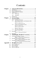
Contents Chapter Chapter 1 General Information ....................................... 2 1.1 1.2 1.3 1.4 Introduction ....................................................................... 2 General Specifications....................................................... 3 Passive Backplane Options ............................................... 4 ATM Series ....................................................................... 5 1.5 Dimensions............................................................
ATM-4008 & ATM-4233 Manual x
CHAPTER 1 General Information 1 Chapter 1
Chapter 1 General Information 1.1 Introduction The ATM-4008 and ATM-4233 Rackmounted series are 4U height 14slot/8-slot rackmount IPC workstations with a 6" LCD display and builtin slim keyboard and touch pad drawer. They are designed as all-in-one and cost-effective solutions for traditional IPC users and new industrial automation control applications.
1.2 General Specifications General • Construction: Heavy duty steel chassis • Drive bay: 3 x vibration damped, front-accessed 5.25" x 2 and 3.5" x 1 • Cooling system: Dual easy-to-replace 84 ~ 114 CFM cooling fans with front-accessible air filters • Controls: Power On/Off Button in front panel (behind the lockable door). Reset Button in front Panel (behind the lockable door).
1.
1.4 ATM Series Model No.
1.4.1 ATM-4008 Model No. Description ATM-4008R1-K 8 ISA slot Industrial Automation platform with 6” LCD /4U /Half Size/Rear Wiring/ PCA-6108E (rev.C1) / 250W Power Supply ATM-4008R1-KC3 8 ISA slot Industrial Automation platform with 6” LCD /4U /Half Size/Rear Wiring/ PCA-6108E (rev.C1) / PCA-6774F-02A1(PIII)/250W Power Supply ATM-4008R2-K 8 PCI slot Industrial Automation platform with 6” LCD /4U /Half Size/Rear Wiring/ PCA-6108P8 (rev.
1.
174.9[6.89] 101.6[4.00] 450.6[17.74] ATM-4233 426[16.77] 465[18.31] Unit : mm [inch] 482[18.
CHAPTER 2 System Setup 9 Chapter 2
Chapter 2 System Setup 2.1 System Installation WARNING: Before starting the installation process, be sure to shut down all power from the chassis. Do this by turning off the power switch, and unplugging the power cord from the power outlet. When in doubt, consult with an experienced technician. 2.1.1 Attaching the Handles. The handles for the front panel are in the accessory box. To install the handles, simply secure them to the front panel with the provided screws. 2.1.
2.1.3 Chassis Front and Rear Sections Face the front of the ATM chassis, and you will find a 6" TFT display module with five membrane control keys on each side. There is a front door on the right side and a slim drawer with a 88-key keyboard under the chassis. The front panel switches and I/O interface behind the door are used for system reset, power switch, USB port and brightness control.
System Reset: Press this switch to reinitialize the system. This is the same as the hardware reset button. Power On/Off Switch: Use this switch to turn on/off the system power. USB port: If you want to connect any USB interface device to the system, you could use this. KB/MB IN: Integrated PS/2 type 6-pin Keyboard and Mouse port. Figure 2.5: Rear View 2.1.4 Drive Bay Installation The Standard Drive Bay of the ATM series can hold CD-ROM, 5.25"(x2) and 3.5" (x1) devices Installation disk drives. a.
e. Insert the drives into their proper locations in the drive bay and secure them with the screws provided. f. Connect the disk drive power and signal cables.
Figure 2.6: Drive Bay 2.2 Keyboard ATM-4008 and ATM-4233 comes with a US version 88-key slim type keyboard, which is located on the button of chassis. The slim type keyboard is integrated with the chassis and has a slide rail on both sides. The keyboard can be pulled out or pushed into the chassis very easily after pressing both latches together. Refer to figure 2-10.. Slide Rail Slide Rail Latch Latch Figure 2.
2.3 Backplane Please refer to figure 2-8 for a suitable cable connection of backplane ATX 20-pin CN2 Alarm PWR Voltages output CN1 PS-ON/GND/5VSV Figure 2.8: Backplane Connections 2.4 Power Supply ATM-4008 and ATM-4233 comes with a power supply bracket. Please use this bracket for PS/2 power and remove this bracket if you want to install a redundant power supply. 2.5 Installing CPU Cards To install slot board computers and other add-on boards: 1. Remove the chassis cover. 2.
3. Insert the SBC or add-on cards on suitable location 4. Connect the cables to the right location of the CPU Card. For example Figure 2-9. 5. Align and fix the screw to tighten the card to a fixed position 6. Return the top cover after fixing the hold down cramp.
CHAPTER 3 LCD Display Module & Accessory 17 Chapter 3
Chapter 3 LCD Display Module & Accessory The LCD display module is located at the left side of the front bezel. It can be moved out from chassis by the following process: a. Unscrew the four screws of the LCD module. Please refer to figure 3.1 for their locations. b. Release the two cables that connect the chassis with the LCD Module. Refer to Figure 3.2. Please move the LCD module toward away from chassis to get enough space putting the LCD module down.
c. Release the cabling which connect with LCD module or undo some screws to open the cover of LCD module to do the necessary process, which you need. 3.1 LCD Display Module Layout User Connector connect w/ SBC Inverter Figure 3.
3.2 Internal K/B and Mouse Board CN1 is connected with a slim type keyboard cable, which is connected with external K/B and mouse board. CN3 is connected with a touch pad board. Refer to figure 3-6 to find the correct location. Figure 3.2: Internal K/B and Mouse Board 3.3 External K/B and Mouse Board The J1 is connecting to CN2 of internal K/B and mouse board. JP2 is connecting with 10 function keys membrane cable. CN2 connect with K/B and Mouse port of SBC by a PS/2 6-pin cable.
Appendix A Backplane Layouts 21 Appendix A
Appendix A Backplane Layouts A.1 PCA-6108P8-0A1 185.00 162.60 154.94 30.80 10.16 19.94 158.30 182.00 18.16 PCI6 43.18 PH20.32*7=142.24 PCI5 19.94 PCI7 PCI8 Ground 164.00 40.64 PCI4 FAN 97.30 7.92 PCI3 154.80 1.60 22 ATM-4008 & ATM-4233 Manual 20.32 PCI2 MASTER KB-OUT 5V-12V 130.60 40.10 10.60 12.80 16.51 PCI1 .00 Ø4 PS-ON 8.50 22.00 48.20 157.70 155.80 157.70 BIG 4P AT ATX ALARM KB-OUT KB-IN 31.12 11.
A.
A.
A.
ATM-4008 & ATM-4233 Manual 26