
User manual


11 SNMP-1000-B2 User Manual
Chapter 2 Hardware Installation
2.2.12 Digital Output Connectors (DO1 ~ DO4)
Alarm events can independently trigger one of four digital output signals. These sig-
nals can be used to control external devices and restore the system health or to
notify users of the alarm-triggering event. This connector is not available on the chas-
sis carrier board.
2.2.13 Alarm Reset Connector (CN17)
This connector is used to reset the alarm after an alarm-triggering event occurs. The
alarm can be connected to an auto-recovery push button (that is activated when the
button is pushed).
2.2.14 LED Indicator Connector (CN18)
The system status can be displayed using LED indicators. CN18 is connected to an
LED indicator board. Please refer to Appendix A regarding pin assignments.
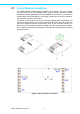
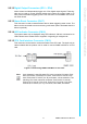
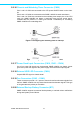
2.2.15 CPU Card Interface Connector (CN19)
This connector can be used to monitor the status of the CPU card. The 8 pin to 6 pin
cable included with the product can be used to connect SNMP-1000-B2 to a CPU
card.
Figure 2.5 Connecting SNMP-1000-B2 to a CPU card
Note Only Advantech’s new full-sized CPU cards, including PCA-6002, PCA-
6003, PCA-6004, PCA-6005, PCA-6181, PCA-6183, PCA-6184, PCA-
6185, PCA-6186, PCA-6277 (rev. B), and newer, can be monitored. The
following CPU cards cannot be monitored: PCA-6155V, PCA-6168,
PCA-6175, PCA-6176, PCA-6178, PCA-6179, PCA-6180, PCA-6275,
PCA-6276, PCA-6277 (rev. A), PCA-6278, PCA-6359, and earlier.