
Specifications
24
PCA-6176 User's Manual
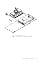
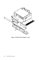
To install the bracket, find an empty slot in your chassis. Unscrew the
plate that covers the end of the slot. Screw in the bracket in place of
the plate. Next, attach the flat-cable connector to CN4 on the CPU
card. Wire 1 of the cable is red or blue, and the other wires are gray.
Make sure that wire 1 corresponds to pin 1 of CN4. Pin 1 is on the
upper right side of CN4.
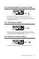
2.4 SCSI Connector (CN5)
The PCA-6176S/F series has a 68-pin, dual in-line connector for
Ultra2 SCSI devices. Connection of SCSI devices requires special
attention, especially when determining the last drive on the SCSI
chain. Refer to Chapter 6 and your device's operating manual for
detailed installation advice.
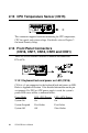
2.5 USB Connector (CN6)
The PCA-6176 CPU card provides one USB (Universal Serial Bus)
interface, which give complete Plug & Play and hot attach/detach for
up to 127 external devices.The USB interface complies with USB
Specification Rev. 1.0, and is fuse-protected.
The USB interface is accessed through a 10-pin flat-cable connector,
CN6. The adapter cable has a 10-pin connector on one end and a USB
connector on the bracket.
The USB interface can be disabled in the system BIOS setup.