PCA-6176 Series Full-size Pentium® II/III processor-based PCI/ISA-bus CPU card
Copyright notice This document is copyrighted, 1999, by Advantech Co., Ltd. All rights are reserved. Advantech Co., Ltd. reserves the right to make improvements to the products described in this manual at any time without notice. No part of this manual may be reproduced, copied, translated or transmitted in any form or by any means without the prior written permission of Advantech Co., Ltd. Information provided in this manual is intended to be accurate and reliable. However, Advantech Co., Ltd.
A Message to the Customer Advantech customer services Each and every Advantech product is built to the most exacting specifications to ensure reliable performance in the harsh and demanding conditions typical of industrial environments. Whether your new Advantech equipment is destined for the laboratory or the factory floor, you can be assured that your product will provide the reliability and ease of operation for which the name Advantech has come to be known. Your satisfaction is our primary concern.
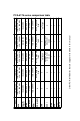
ü 4 ü ü 2 4 ü HISA USB EIDE 2S/1P ü 4 2 ü 4 2 ü Other PCA-6176 Series features appear elsewhere in this manual 2 ü x Adaptec 7890 Ultra2 SCSI 32-bit Adaptec 7890 Ultra2 SCSI 32-bit x x SCSI 10/100Base-T, Intel 82558 x x 10/100Base-T, Intel 82558 x LAN ü 4 2 ü ATI 3D Rage Pro Turbo ATI 3D Rage Pro Turbo 1 GB SDRAM 512 KB Award, P&P Intel 440 BX ATI 3D Rage Pro Turbo 1 GB SDRAM 512 KB Award, P&P Intel 440 BX PCA-6176E Intel: Pentium® II/III 350 ~ 500 MHz ATI 3D Ra
Product warranty Advantech warrants to you, the original purchaser, that each of its products will be free from defects in materials and workmanship for one year from the date of purchase. This warranty does not apply to any products which have been repaired or altered by persons other than repair personnel authorized by Advantech, or which have been subject to misuse, abuse, accident or improper installation. Advantech assumes no liability under the terms of this warranty as a consequence of such events.
Initial Inspection Before you begin installing your card, please make sure that the following materials have been shipped: • 1 PCA-6176 Pentium® II/III single board computer • 1 Pentium II/III CPU, and 1 cooling fan (optional) • 1 PCA-6176 User's Manual • Utility disks/CD with VGA BIOS • 2 Ethernet driver disks/CD (PCA-6176E/F only) • SCSI driver disks/CD (PCA-6176S/F only) • 1 bus master driver disk/CD • 2 disks/CD for OBS Win95 drivers • 1 FDD cable • 2 EIDE HDD cables • 1 printer cable and 1 serial port
As you unpack the PCA-6176, check it for signs of shipping damage. (For example, damaged box, scratches, dents, etc.) If it is damaged or it fails to meet the specifications, notify our service department or your local sales representative immediately. Also notify the carrier. Retain the shipping carton and packing material for inspection by the carrier. After inspection, we will make arrangements to repair or replace the unit.
Contents Chapter 1 Hardware Configuration .............................. 1 1.1 1.2 1.3 Introduction ........................................................................2 Features ...............................................................................3 Specifications ......................................................................4 System ..................................................................................4 Memory ..............................................................
Chapter 2 Connecting Peripherals ............................ 21 2.1 2.2 2.3 2.4 2.5 2.6 2.7 2.8 2.9 2.10 2.11 2.12 2.13 2.14 2.15 Primary (CN1) and Secondary (CN2) IDE Connectors ........................................................................22 Floppy Drive Connector (CN3) .......................................23 Parallel Port Connector (CN4) .......................................23 SCSI Connector (CN5) ....................................................24 USB Connector (CN6) ................
3.5 3.6 3.7 3.8 3.9 3.10 3.11 3.12 3.13 3.14 3.4.4 Boot Up Floppy Seek ................................................35 3.4.5 Boot Up NumLock Status .........................................36 3.4.6 Gate A20 Option .......................................................36 3.4.7 Typematic Rate Setting .............................................36 3.4.8 Typematic Rate (Chars/Sec) .....................................36 3.4.9 Typematic Delay (msec) ...........................................36 3.4.
Chapter 5 LAN Configuration ..................................... 59 5.1 5.2 5.3 5.4 5.6 Introduction ......................................................................60 Features .............................................................................60 Drivers Installation ..........................................................61 Windows 95/98 Drivers Setup Procedure ......................62 Windows NT Drivers Setup Procedure ..........................
Appendix A Programming the Watchdog Timer ....... 99 A.1 Programming the Watchdog Timer .............................100 Appendix B Pin Assignments .................................. 103 B.1 B.2 B.3 B.4 B.5 B.6 B.7 B.8 B.9 B.10 B.11 B.12 B.13 B.14 B.15 B.16 B.17 B.18 B.19 B.20 B.21 B.22 IDE Hard Drive Connector (CN1, CN2) ......................104 Floppy Drive Connector (CN3) .....................................105 Parallel Port Connector (CN4) .....................................
CHAPTER 1 Hardware Configuration This chapter gives background information on the PCA-6176. It then shows you how to configure the card to match your application and prepare it for installation into your PC.
1.1 Introduction The PCA-6176 series all-in-one industrial grade CPU card uses Intel's highly acclaimed Pentium® II/III processor, together with the Intel 440BX PCI chipset. The card works with standard ISA or PCI/ISA-bus passive backplanes. The CPU provides 512 KB on-chip L2 cache, eliminating the need for external SRAM chips. It has two PCI EIDE interfaces (for up to four devices), and an FDD interface (for up to two devices).
1.
1.3 Specifications System • CPU: Intel Pentium® II/III up to 500 MHz • BIOS: Award Flash BIOS, 2 Mbit • Green function: Supports power management operation via BIOS. Activated by keyboard or mouse activity • PCI enhanced IDE hard disk drive interface: Supports up to four IDE (AT bus) large hard disk drives, or other enhanced IDE devices. Supports PIO Mode 4 (16.67 MB/s data transfer rate) and Ultra DMA/33 (33 MB/s data transfer rate).
• Serial ports: Two RS-232 ports with 16C550 UARTs (or compatible) with 16-byte FIFO buffer. Supports speeds up to 115.2 Kbps. Ports can be individually configured to COM1, COM2 or disabled • Keyboard and PS/2 mouse connector: A 6-pin mini-DIN connector is located on the mounting bracket for easy connection to a keyboard or PS/2 mouse.
Mechanical and environmental specifications • Operating temperature: 0 ~ 60° C (32 ~ 140° F) • Storage temperature: -40 ~ 60° C (-40 ~ 140° F) • Humidity: 20 ~ 95% non-condensing • Power supply voltage: +5 V, ±12 V • Power consumption: +5 V @ 6.93 A (for Pentium® II 233 MHz) +5 V @ 8.4 A (for Pentium® II 300 MHz) +5 V @ 5.71 A (for Pentium® II 400 MHz) +5 V @ 6.22 A (for Pentium® II 450 MHz) +12 V @ 0.2 A (typical) -12 V @ 0.05 A (typical) • Board size: 338 x 122 mm (13.3" x 4.8") • Board weight: 0.5 kg (1.
Intel 82440BX PCI set Four DIMM modules up to 1 GB ATX power control connector Parallel port VGA (AGP) connector LAN connector COM2 connector USB COM1 PS/2 mouse connector & keyboard connector Ultra2 SCSI connector FDD connector EIDE connectors CPU temperature sensor connector 1.
1.5 Jumpers and Connectors Connectors on the PCA-6176 board link it to external devices such as hard disk drives and a keyboard. In addition, the board has a number of jumpers used to configure your system for your application. The tables below list the function of each of the board jumpers and connectors. Later sections in this chapter give instructions on setting jumpers. Chapter 2 gives instructions for connecting external devices to your card.
Table 1-2: Connectors Label CN1 CN2 CN3 CN4 CN5 CN6 CN7 CN8 CN9 CN10 CN11 CN12 CN13 CN14 CN15 CN16 CN17 CN18 CN19 CN20 CN21 CN22 Function Primary IDE connector Secondary IDE connector Floppy driver connector Parallel port SCSI connector USB port VGA connector Ethernet connector Serial port: COM1 Serial port: COM2 PS /2 keyboard and mouse External keyboard connector Infrared (IR) connector CPU fan connector CPU temperature sensor Keyboard lock and power LED External speaker Reset connector IDE LED ATX feat
1.
1.7 Safety Precautions Warning! Always completely disconnect the power cord from your chassis whenever you work with the hardware. Do not make connections while the power is on. Sensitive electronic components can be damaged by sudden power surges. Only experienced electronics personnel should open the PC chassis. Caution! Always ground yourself to remove any static charge before touching the CPU card. Modern electronic devices are very sensitive to static electric charges.
1.8 Jumper Settings This section provides instructions on how to configure your card by setting jumpers. It also includes the card's default settings and your options for each jumper. 1.8.1 How to set jumpers You configure your card to match the needs of your application by setting jumpers. A jumper is the simplest kind of electric switch. It consists of two metal pins and a small metal clip (often protected by a plastic cover) that slides over the pins to connect them.
1.8.3 CMOS clear (J1) The PCA-6176 CPU card contains a jumper that can erase CMOS data and reset the system BIOS information. Normally this jumper should be set with pins 1-2 closed. If you want to reset the CMOS data, set J4 to 2-3 closed for just a few seconds, and then move the jumper back to 1-2 closed. This procedure will reset the CMOS to its default setting. Table 1-4: CMOS clear (J1) Function Jumper setting * Keep CMOS data 1-2 closed Clear CMOS data 2-3 closed 1 1 * default setting 1.8.
1.9 System Memory The top-left edge of the PCA-6176 contains four sockets for 168-pin dual inline memory modules (DIMMs). All four sockets use 3.3 V unbuffered synchronous DRAMs (SDRAM). DIMMs are available in capacities of 16, 32, 64, 128, or 256 MB. The sockets can be filled in any combination with DIMMs of any size, giving your PCA-6176 single board computer between 16 MB and 1 GB of memory.
1.9.2 Supplementary information about DIMMs Your PCA-6176 can accept SDRAM memory chips (with or without parity). Also note: • If the PCA-6176 operates at 100 MHz, only use PC100-compliant DIMMs. Most systems will not even boot if non-compliant modules are used. This is due to strict timing issues involved at this speed. • SDRAM chips are usually thinner than EDO chips, and they usually have higher pin density. • Chips with 9 chips/side support ECC; chips with 8 chips/side do not support ECC.
1.10 Memory Installation Procedures To install any DIMM, first make sure the two handles of the DIMM socket are in the "open" position. i.e. The handles lean outward. Slowly slide the DIMM module along the plastic guides on both ends of the socket. Then press the DIMM module right down into the socket, until you hear a click. This is when the two handles have automatically locked the memory module into the correct position of the DIMM socket. (See Figure 1-3.
1.11 Cache Memory Since second level cache has been embedded into the Pentium® II/III CPU, you do not have to take care of either SRAM chips or SRAM modules. The built-in second level cache in the Pentium II/III yields much higher performance than external cache memories. The cache size in the Pentium II/III CPU is either 256 KB or 512 KB. Normally, for workstation and server applications, the 256 KB version is suffucient.
1.12 Mounting the CPU and Cooling Modules The Pentium® II/III is a module-type CPU which runs at high speeds, for example 450 MHz, so the cooling mechanism becomes critical for system reliability. There are two types of cooling systems. One has a cooling fan attached to the heat sink of the Pentium II/III module. The other has a huge heat sink without any cooling fan attached. The first of these systems is recommended.
Figure 1-5: SECC II CPU installation - step 1 Chapter 1 Hardware Configuration 19
Figure 1-6: SECC II CPU installation - step 2 20 PCA-6176 User's Manual
CHAPTER 2 Connecting Peripherals This chapter tells how to connect peripherals, switches and indicators to the PCA-6176 board. You can access most of the connectors from the top of the board while it is installed in the chassis. If you have a number of cards installed, or your chassis is very tight, you may need to partially remove the card to make all the connections.
2.1 Primary (CN1) and Secondary (CN2) IDE Connectors CN1 CN 2 You can attach up to four IDE (Integrated Device Electronics) drives to the PCA-6176’s internal controller. The primary (CN1) and secondary (CN2) connectors can each accommodate two drives. Wire number 1 on the cable is red or blue and the other wires are gray. Connect one end to connector CN1 or CN2 on the CPU card. Make sure that the red/blue wire corresponds to pin 1 on the connector (in the upper right hand corner).
2.2 Floppy Drive Connector (CN3) You can attach up to two floppy disk drives to the PCA-6176's on-board controller. You can use any combination of 5.25" (360 KB/1.2 MB) and/or 3.5" (720 KB/1.44/2.88 MB) drives. The card comes with a 34-pin daisy-chain drive connector cable. On one end of the cable is a 34-pin flat-cable connector. On the other end are two sets of floppy disk drive connectors. Each set consists of a 34-pin flat-cable connector (usually used for 3.
To install the bracket, find an empty slot in your chassis. Unscrew the plate that covers the end of the slot. Screw in the bracket in place of the plate. Next, attach the flat-cable connector to CN4 on the CPU card. Wire 1 of the cable is red or blue, and the other wires are gray. Make sure that wire 1 corresponds to pin 1 of CN4. Pin 1 is on the upper right side of CN4. 2.4 SCSI Connector (CN5) The PCA-6176S/F series has a 68-pin, dual in-line connector for Ultra2 SCSI devices.
2.6 VGA Connector (CN7) The PCA-6176E/S/F PCI SVGA interface can drive conventional CRT displays. CN7 is a standard 15-pin D-SUB connector commonly used for VGA. Pin assignments for CRT connector CN7 are detailed in Appendix B. 2.7 Ethernet Connector (CN8) The PCA-6176E/F is equipped with a high performance 32-bit PCI-bus Ethernet interface, which is fully compliant with IEEE 802.3 10/100 Mbps CSMA/CD standards.
Table 2-1: Serial port connections (COM1, COM2) Connector Ports Address Interrupt CN9 COM1 3F8*, 3E8 IRQ4 CN10 COM2 2F8*, 2E8 IRQ3 * default settings The IRQ and address ranges for both ports are fixed. However, if you want to disable the port or change these parameters later, you can do this in the system BIOS setup. Different devices implement the RS-232 standard in different ways. If you are having problems with a serial device, be sure to check the pin assignments for the connector. 2.
2.10 External Keyboard Connector (CN12) In addition the the PS/2 mouse/keyboard connector on the PCA-6176's rear plate, there is also an extra on-board external keyboard connector. This gives system integrators greater flexibility in designing their systems. 2.11 IR Connector (CN13) This connector supports the optional wireless infrared transmitting and receiving module. This module mounts on the system case. You must configure the setting through the BIOS setup. 2.
2.13 CPU Temperature Sensor (CN15) This connector supports hardware monitoring for CPU temperature, CPU fan speed, and system voltage. For details, refer to Chapter 7: On-board Security Setup. 2.14 Front Panel Connectors (CN16, CN17, CN18, CN19 and CN21) There are several external switches to monitor and control the PCA-6176. 2.14.1 Keyboard lock and power on LED (CN16) CN16 is a 5-pin connector for the keyboard lock and power on LED.
2.14.2 External speaker (CN17) CN17 is a 4-pin connector for an extenal speaker. If there is no external speaker, the PCA-6176 provides an on-board buzzer as an alternative. To enable the buzzer, set pins 3-4 as closed. 2.14.3 Reset (CN18) Many computer cases offer the convenience of a reset button. Connect the wire from the reset button to CN18. 2.14.4 IDE LED (CN19) You can connect an LED to connector CN19 to indicate when the HDD is active. 2.14.
1. Take the specially designed ATX-to-PS/2 power cable out of the PCA-6176's accessory bag. 2. Connect the 3-pin plug of the cable to CN20 (ATX feature connector). 3. Connect the power on/off button to CN21. (A momentary type of button should be used.) Note: If you do not use an ATX power connector, make sure that pins 2-3 are closed. Warnings: 1. Make sure that you unplug your power supply when adding or removing expansion cards or other system components.
CHAPTER 3 Award BIOS Setup This chapter describes how to set the card’s BIOS configuration data.
3.1 Introduction Award’s BIOS ROM has a built-in setup program that allows users to modify the basic system configuration. This type of information is stored in battery-backed RAM so that it retains the setup information when the power is turned off. 3.2 Entering Setup Turn on the computer and check for the "patch code". If there is a number assigned to the patch code, it means that the BIOS supports your CPU.
3.3 Standard CMOS Setup Choose the “STANDARD CMOS SETUP” option from the "INITIAL SETUP SCREEN" menu, and the screen below will be displayed. This standard setup menu allows users to configure system components such as date, time, hard disk drive, floppy drive, display, and memory.
3.4 BIOS Features Setup The “BIOS FEATURES SETUP” screen appears when choosing the "BIOS FEATURES SETUP" item from the "CMOS SETUP UTILITY" menu. It allows the user to configure the PCA-6176 according to his particular requirements. Below are some major items that are provided in the BIOS FEATURES SETUP screen. A quick booting function is provided for your convenience. Simply enable the Quick Booting item to save yourself valuable time. Figure 3-2: BIOS features setup screen 3.4.
3.4.2 Quick Power On Self Test This option speeds up the Power-On Self Test (POST) conducted as soon as the computer is turned on. When enabled, BIOS shortens or skips some of the items during the test. When disabled, the computer conducts normal POST procedures. 3.4.3 Boot Sequence This function determines the sequence in which the computer will search the drives for the disk operating system (i.e. DOS).
3.4.5 Boot Up NumLock Status The default is “On”. On Keypad boots up to number keys. Off Keypad boots up to arrow keys. 3.4.6 Gate A20 Option Normal The A20 signal is controlled by the keyboard controller or chipset hardware. Fast (Default) The A20 signal is controlled by Port 92 or the chipset specific method. 3.4.7 Typematic Rate Setting The typematic rate determines the characters per second accepted by the computer. The Typematic Rate setting enables or disables the typematic rate. 3.4.
Note: To disable security, select "PASSWORD SETTING" in the main menu. At this point, you will be asked to enter a password. Simply press to disable security. When security is disabled, the system will boot, and you can enter Setup freely. 3.4.11 PCI/VGA Palette Snoop Some display cards that are nonstandard VGA such as graphics accelerators or MPEG video cards may not show colors properly. The setting Enabled should correct this problem.
3.5 Chipset Features Setup By choosing the “CHIPSET FEATURES SETUP” option from the INITIAL SETUP SCREEN menu, a screen as shown in Fig. 3-3 below will be displayed. This sample screen contains the manufacturer’s default values for the PCA-6176. If you enable the OBS function, you can view the temperature, fan speed and voltage of your PC system. The data will be displayed in similar fashion to the display shown in Fig.
3.6 Power Management Setup The power management setup controls the CPU card's “green” features. The following screen shows the manufacturer’s defaults: Figure 3-4: Power management setup screen 3.6.1 Power Management This option allows you to determine if the values in power management are disabled, user-defined, or predefined. 3.6.2 HDD Power Management You can choose to turn the HDD off after one of the time intervals listed, or when the system is in Suspend mode.
3.6.3 Soft-Off by PWR-BTTN If you choose "Instant-Off", then pushing the ATX soft power switch button once will switch the system to "system off" power mode. You can choose "Delay 4 sec." If you do, then pushing the button for more than 4 seconds will turn off the system, whereas pushing the button momentarily (for less than 4 seconds) will switch the system to "suspend" mode. 3.
3.7.1 IRQ-xx assigned to : PCI/ISA PnP These fields indicate whether or not the displayed IRQ for each field is being used by a legacy (non-PnP) card. Two options are available: PCI/ISA PnP or Legacy ISA. The first option, the default setting, indicates that the displayed IRQ is not used to determine if an ISA card is using that IRQ. If you install a legacy ISA card that requires a unique IRQ, you must set the field for that IRQ to "Legacy ISA".
3.8 Load BIOS Defaults “LOAD BIOS DEFAULTS” indicates the most appropriate values for the system parameters for maximum stability. These default values are loaded automatically if the stored record created by the setup program becomes corrupted (and therefore unusable). 3.9 Load Setup Defaults “LOAD SETUP DEFAULTS” loads the values required by the system for maximum performance. 3.
3.11 Password Setting To change the password: 1. Choose the "PASSWORD SETTING" option from the Setup main menu and press . The screen will display the following message: Enter Password: Press . 2. If the CMOS is good, or if this option has been used to change the default password, the user is asked for the password stored in the CMOS. The screen will display the following message: Confirm Password: Enter the current password and press . 3.
3.13 Save & Exit Setup If you select this and press , the values entered in the setup utilities will be recorded in the CMOS memory of the chipset. The microprocessor will check this every time you turn your system on and compare this to what it finds as it checks the system. This record is required for the system to operate. 3.14 Exit Without Saving Selecting this option and pressing lets you exit the setup program without recording any new values or changing old ones.
CHAPTER 4 AGP VGA Setup The PCA-6176 series features an on-board AGP VGA interface. This chapter provides instructions for installing and operating the software drivers on the display driver disk/CD included in your package.
4.1 Before you begin To facilitate the installation of the enhanced display device drivers and utility software, you should read the instructions in this chapter carefully before you attempt installation. The enhanced display drivers for the PCA-6176 series board are located on the software installation diskette. You must install the drivers and utility software by using the supplied SETUP program for DOS drivers. Note: The files on the software installation diskette are compressed.
• Power management for full VESA DPMS and EPA Energy Star compliance • User-friendly installation for Windows 95 and Windows NT • AGP 1.0 interface • 4 MB, 164-bit, 100 MHz SGRAM frame buffer interface with 800 MB/sec bus bandwidth • Integrates superior video features. These include filtered sealing of 720 pixel DVD content, and MPEG-2 motion compensation for software DVD 4.3 Installation Disk 1 (or CD): Disk ATI RAGE PRO TURBO - AGP/VGA for Win95/98 - #1 V1.
4.4 Driver installation Necessary prerequisites The instructions in this manual assume that you understand elementary concepts of MS-DOS and the IBM personal computer. Before you attempt to install any driver or utility, you should know how to copy files from a floppy disk/CD to a directory on the hard disk. You should also understand the MS-DOS directory structure, and know how to format a floppy disk.
4.5 Windows 95/98 Drivers Setup Procedure Note 1: There are two ways to set up the PCA-6176's VGA. You can follow the procedures in this chapter, or you can use the setup function provided by Windows 95 or Windows 98. Note 2: If you follow the procedures in this chapter, you must use Disk 1 (provided in your PCA-6176 kit). 1. In the Windows 95/98 screen, click "Start". Select "Settings", and then click the "Control Panel" icon. 2.
3. If you choose "Yes (Recommended)" and press "Next", the Hardware Wizard will help you find the new hardware. If the Hardware Wizard cannot find the new hardware, or if you want to set up the VGA driver by yourself, select "No, I want to select the hardware from a list", and press "Next". 4. In the "Hardware types" list, select "Display adapters" and press "Next".
5. Insert disk #1 and select "Have Disk". 6. Click "OK".
7. Select "macxw4.inf" and click "OK". 8. Select "RAGE PRO TURBO AGP (English)" and click "OK".
9. Click "Next". 10. Insert disk # 2 and click "OK".
11. Insert disk # 3 and click "OK". 12. Click "Finish" to complete the setup procedure.
4.6 Windows NT Drivers Setup Procedure 1. In the "Control Panel" screen, select the "Display" icon and click "Display Type". 2. Click "Change".
3. Click "Have Disk". 4. Click "Browse" to look for the driver program.
5. Select "atirage" and click "Open". 6. Select "ATIRAGE PRO TURBO AGP 2X" and click "OK".
7. When the driver has been successfully installed, click "OK". 8. Click "Yes" to restart your computer and enable the changes to take effect.
CHAPTER 5 LAN Configuration The PCA-6176E/F features an on-board LAN interface. This chapter gives detailed information on Ethernet configuration. It shows you how to configure the card to match your application requirements.
5.1 Introduction The PCA-6176E/F features an optional 32-bit 10/100 Mbps Ethernet network interface. This interface supports bus mastering architecture and auto-negotiation features. Therefore standard twisted-pair cabling with RJ-45 connectors for both 10 Mbps and 100 Mbps connections can be used. Extensive driver support for commonly-used network systems is also provided. 5.
5.3 Drivers Installation The PCA-6176E/F's on-board Ethernet interface supports all major network operating systems. The BIOS automatically detects the LAN while booting, and assigns an IRQ level and I/O address. No jumpers or switches are required for user configuration.
5.4 Windows 95/98 Drivers Setup Procedure 1. In the Windows 95/98 screen, click "Start". Select "Settings", and then click the "Control Panel" icon. 2. Click "Next".
3. Click "Next". 4. Click "Next".
5. Follow the instructions on the screen and click "Have Disk". 6. Click "Browse".
7. Select "net82557.inf" and click "OK". 8. Click "OK".
9. Click "OK". 10. Click "Next".
11. Click "Finish". 12. Click "Yes".
5.6 Windows NT Drivers Setup Procedure Note: You must install your Windows NT drivers before you begin to connect up your LAN wiring. Otherwise LAN irregularities may occur. 1. In the "Windows NT" screen, click "Start" and select "Settings". Then click the "Control Panel" icon to select "Network". 2. Click "No".
3. Click "Add" to add your new driver. 4. Select "Have Disk" to find the Network Adapters Driver program.
5. Click "OK". 6. Select "Intel(R) PRO Adapter" and click "OK".
7. You will then find the new network adapter "Intel 8255x-based PCI Ethernet Adapter (10/100)" in Windows.
72 PCA-6176 User's Manual
CHAPTER 6 SCSI Setup and Configurations The PCA-6176S/F features an on-board SCSI interface. This chapter explains basic SCSI concepts, and provides instructions for installing the software drivers with the SCSI driver disks/CD included in your package. For more details, refer to the “Adaptec 7800 Family Manager Set” User’s Guide.
6.1 Introduction The PCA-6176S/F is equipped with an Adaptec AIC-7890 single-chip PCI-to-SCSI host adapter which provides a powerful Ultra2 multitasking interface between your computer’s PCI bus and SCSI devices (disk drives, CD-ROM drives, scanners, tape backups, removable media drives, etc.). Up to a total of 15 SCSI devices can be connected to the SCSI connector on AIC-7890. The Adaptec AIC-7890 is a 16-bit, LVD/SE (Low Voltage Differential/Single-Ended) SCSI solution for your computer.
The SCSI Select screen will come up. Instructions on how to move the cursor and select options are listed at the bottom of the program windows. You can select either Configure/View Host Adapter Settings or SCSI Disk Utilities. 6.3 SCSI Terminators To ensure reliable communication, the SCSI bus must be properly terminated. Termination is controlled by a set of electrical resistors, called terminators. Terminators must be placed (or enabled) at the two extreme ends of the SCSI bus.
6.4 Adaptec EZ-SCSI Utility Adaptec EZ-SCSI gives you what you need to use your SCSI devices most effectively with Windows 95 and Windows NT. You can also use Adaptec EZ-SCSI on computers running DOS, Windows 3.1x, or Windows for Workgroups 3.1x. 6.4.1 Quick start instructions First, install the SCSI devices (see the hardware documentation for details). Then follow the instructions for your operating system software in one of the following sections.
6.4.3 Windows / Windows for Workgroups 3.1x 1. Install Windows 3.1x or Windows for Workgroups 3.1x, and start it running on your computer. 2. Insert the Adaptec EZ-SCSI Setup diskette into your floppy disk drive. 3. Select File/Run from the Program Manager menu. 4. When the Run dialog box appears, type a:\setup if you are using the A: drive or b:\setup if you are using the B: drive. Then click OK. 5. Follow the instructions that appear on the screen. 6.4.4 DOS 1. Install DOS 6.
6.4.6 Windows 95 / Windows NT troubleshooting What is a miniport driver, and how do I make sure that the miniport driver is installed correctly? Miniport drivers are a new kind of 32-bit protect mode device driver used by Windows 95 and Windows NT to control host adapters and other kinds of devices. Windows 95 and Windows NT include a set of miniport drivers for various types of SCSI host adapters.
What if a yellow exclamation point or a red X appears in Device Manager in front of my host adapter? 1. Open the Control Panel, double-click on System, and click the Device Manager tab. 2. Double-click the SCSI Controllers icon, select the name of the old host adapter, and click Remove. 3. Turn off the computer and physically remove the currently installed host adapter. 4. Install the new host adapter according to the instructions in the hardware documentation. 5. Turn the computer on.
My CD-ROM drive does not work properly under Windows 95. Some older models of SCSI CD-ROM drives are not compatible with the embedded Windows 95 CD-ROM driver. You can add support for the CD-ROM drive by doing the following: 1. Click the Start button and select Restart the Computer in MS-DOS mode. 2. When the DOS prompt appears, follow the Quick Start instructions for DOS. 3. When you have finished running Adaptec EZ-SCSI for DOS, find the file named cdtsd.
6.4.8 DOS and Windows 3.1x device drivers Device drivers are software programs that enable your computer to communicate with SCSI devices such as hard disk drives, CD-ROM drives, and scanners. Each kind of device requires a different device driver. Adaptec EZ-SCSI includes several DOS/Windows 3.1x device drivers that are copied to your hard disk during installation. If Adaptec EZ-SCSI finds these kinds of devices on your computer, it adds command lines to your config.sys and autoexec.
Run scsifmt from the DOS prompt, not from the Windows MS-DOS prompt. Before you run it, make sure that the disk devices you want to format are connected to the host adapter and are powered on. Then follow these steps: 1. Change to the directory where scsifmt.exe is located (usually c:\scsi), type scsifmt at the DOS prompt, and press Enter. Note: If you are formatting a SCSI disk device that supports more than one LUN (for example, Iomega’s Bernoulli dual multidrive), type scsifmt/L at the command line.
Formatter and partitioner (afdisk) Use the DOS-based afdisk utility to partition and format SCSI hard disk drives, Floptical® drives, and magneto-optical drives. You can also use afdisk to remove DOS and non-DOS partitions from a disk drive, and to format removable media in standard hard disk format, OS/2 floppy format, or DOS V (Japanese) format. Note: Use afdisk only if the disk device is not controlled by the host adapter BIOS.
3. To create a new partition on the disk device, press Ins. The “Create a DOS Partition” window appears in the lower right of the screen and suggests that you create one partition on the disk device, equal to its entire capacity. If this is what you want to do, skip to Step 5. 4. To change the size of the partition, use the arrow keys to select Start Cylinder and End Cylinder, and type in the numbers you want. Partitions up to 2 GB are supported. 5. When the number of cylinders is what you want, press Esc.
CHAPTER 7 On-board Security Setup This chapter explains OBS concepts and provides instructions for installing the relevant software drivers. This is done using the OBS driver disks/CD included in your PCA-6176 package.
7.1 Introduction On-board security (OBS) functions monitor key hardware. They help you maintain your system's stability and durability. The PCA-6176 can monitor 5 sets of system positive voltages, 2 sets of system negative voltages, CPU cooling fan speed, and CPU temperature. The positive system voltage sets which can be monitored include: • CPU core voltage: 1.3 V ~ 3.3 V, according to Intel specifications • Transmission voltage from CPU to chipset: typically 1.5 V • Chipset voltage: typically 3.
7.3 Driver Installation 7.3.1 Necessary prerequisites The instructions in this manual assume that you understand elementary concepts of MS-DOS and the IBM personal computer. Before you attempt to install any driver or utility, you should know how to copy files from a floppy disk/CD to a directory on the hard disk. You should also understand the MS-DOS directory structure, and know how to format a floppy disk.
7.3.3 Windows 95/98 drivers setup procedure 1. Insert the OBS driver disk into drive A:. Type: A:\setup.exe Press to run the driver SETUP program.
2. If your operating system is Win95/98, you will see the following screen images after running the driver. You must then reboot your system, start the procedure from Step 1 again, and then proceed directly to Step 3.
Figure 7-3: Restarting Windows 90 PCA-6176 User's Manual
3. Follow the screen instructions to install the software.
4. Complete the setup.
5. Using your file manager, click on "Hardware Doctor" in drive C:, and then click on "W83781".
6. It is recommended that you load the default values for all the OBS settings. However, if desired, you can establish new conditions for voltage, fan speed and temperature.
7. "Winbond Hardware Doctor" will show an icon on the right side of the bottom window bar. This icon is the "Terminate and Stay Resident" (TSR) icon. It will permanently remain in the bottom window bar, and will activate warning signals when triggered by the on-board security system.
8. Click on "Setting", then "Monitoring Config." While enabling each OBS function, you can choose "Faults 1". This will result in a warning message being delivered as soon as any monitored reading exceeds safe limits for the first time. Alternatively, you can set up "Count 3". This will result in a warning message being delivered only after any monitored reading exceeds safe limits for a third time. It is recommended that you load the default settings for all the OBS functions.
9. After completing the setup, all the OBS functions are permanently enabled. When a monitored reading exceeds safe limits, a warning message will be displayed and an error beep tone will be activated to attract your attention.
98 PCA-6176 User's Manual
APPENDIX A Programming the Watchdog Timer The PCA-6176 is equipped with a watchdog timer that resets the CPU or generates an interrupt if processing comes to a standstill for any reason. This feature ensures system reliability in industrial standalone or unmanned environments.
A.1 Programming the Watchdog Timer To program the watchdog timer, you must write a program which writes I/O port address 443 (hex). The output data is a time interval value. The value range is from 01 (hex) to 3F (hex), and the related time interval is 1 sec. to 63 sec. 100 Data Time Interval 01 1 sec. 02 2 sec. 03 3 sec. 04 4 sec. • • • • • • 3F 63 sec.
After data entry, your program must refresh the watchdog timer by rewriting I/O port 443 (hex) while simultaneously setting it. When you want to disable the watchdog timer, your program should read I/O port 443 (hex).
102 PCA-6176 User's Manual
APPENDIX B Pin Assignments This appendix contains information of a detailed or specialized nature.
B.1 IDE Hard Drive Connector (CN1, CN2) 39 37 .... 3 1 40 38 ....
B.2 Floppy Drive Connector (CN3) 33 31 .... 3 1 34 32 ....
B.3 Parallel Port Connector (CN4) 13 12 .... 2 1 26 25 ....
B.4 SCSI Connector (CN5) 34 33 68 67 .... 2 1 ....
B.5 USB Connector (CN6) 1 2 9 10 USB1/USB2 connector (CN6) Pin USB1 Signal Pin USB2 Signal 1 +5 V 2 +5 V 3 UV- 4 UV- 5 UV+ 6 UV+ 7 GND 8 GND 9 Chassis GND 10 Key B.
B.7 Ethernet 10Base-T RJ-45 Connector (CN8) Ethernet 10Base-T RJ-45 connector (CN8) Pin Signal 1 XMT+ 2 XMT- 3 RCV+ 4 N/C 5 N/C 6 RCV- 7 N/C 8 N/C B.
B.9 Keyboard and Mouse Connnector (CN11) Keyboard and mouse connector (CN11) Pin Signal 1 KB DATA 2 MS DATA 3 GND 4 V CC 5 KB CLOCK 6 MS CLOCK B.10 External Keyboard Connector (CN12) External keyboard connector (CN12) Pin Signal 1 CLK 2 DATA 3 NC 4 GND 5 V CC B.
B.12 CPU Fan Power Connector (CN14) 1 2 3 CPU fan power connector (CN14) Pin Signal 1 GND 2 +12 V 3 Detect B.13 Power LED and Keylock Connector (CN16) You can use an LED to indicate when the CPU card is on. Pin 1 of CN16 supplies the LED's power, and Pin 3 is the ground. You can use a switch (or a lock) to disable the keyboard so that the PC will not respond to any input. This is useful if you do not want anyone to change or stop a program which is running.
B.14 External Speaker (CN17) The CPU card has its own buzzer. You can also connect it to the external speaker on your computer chassis. External speaker (CN17) Pin Function 1 +5 V CC 2 GND 3 Internal buzzer 4 Speaker out B.15 Reset Connector (CN18) 1 2 Reset connector (CN18) Pin Signal 1 GND 2 Reset B.
B.
B.18 System I/O Ports System I/O ports Addr.
B.19 DMA Channel Assignments DMA channel assignments Channel Function 0 Available 1 Available 2 Floppy disk (8-bit transfer) 3 Available 4 Cascade for DMA controller 1 5 Available 6 Available 7 Available B.
B.21 1st MB Memory Map 1st MB memory map Addr. range (Hex) Device F0000h - FFFFFh System ROM C8000h - EFFFFh Unused C0000h - C7FFFh VGA BIOS B8000h - BFFFFh CGA/EGA/VGA text B0000h - B7FFFh Unused A0000h - AFFFFh EGA/VGA graphics 00000h - 9FFFFh Base memory B.