
User manual


MIO-9290 User Manual 10
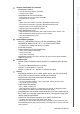
2.1 Jumpers and Switches
The MIO-9290 has a number of jumpers and switches that allow you to configure
your system to suit your application. The table below lists the functions of the various
jumpers.
* DDR3/DDR3L default is auto select, but have an option that can select as DDR3/
DDR3L by jumper.
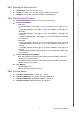
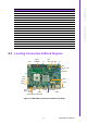
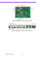
2.2 Connectors
Onboard connectors link the MIO-9290 to external devices such as hard disk drives,
a keyboard, or floppy drives. The table below lists the function of each of the board's
connectors.
Table 2.1: Jumpers
J1 DDR3/DDR3L Setting *
J2 Auto Power On Setting
J3 COM4 RS232/422/485 Setting
J4 COM4 RS232/422/485 Setting
J5 COM4 RS232/422/485 Setting
J6 COM3 RS232/422/485 Setting
J7 COM4 RS232/422/485 Setting
J8 COM3 RS232/422/485 Setting
J9 Clear CMOS
J10 LCD Power
Table 2.2: Switches
SW1 COM4 RS485 TERMINATION PU/PD
SW2 COM3 RS485 TERMINATION PU/PD
SW5 CN38 PCIE/ mSATA SELECTION
SW6 CN29 PCIE/ mSATA SELECTION
Table 2.3: Connectors
Label Function
CN1 12V Power Input
CN2 COM3/COM4
CN3 COM1/COM2
CN5 Audio
CN7 COM5 TX/RX
CN8 COM6 TX/RX
CN14 CPU Socket
CN15 CPU FAN
CN16 Reset
CN17 Power Switch
CN18 48 bits LVDS Panel
CN19 System FAN
CN20 SMBus
CN21 Inverter Power Output