
User manual


9 MIO-2261 User Manual
Chapter 2 H/W Installation
2.2 Connectors
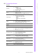
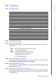
2.2.1 Connector list
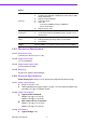
2.2.2 Connector Settings
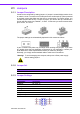
2.2.2.1 Battery Connector (BH1)
MIO-2261 supports Lithium 3 V/210 mAH CR2032 battery with wire via battery con-
nector (BH1).
2.2.2.2 12 V Power Input Connector (CN1)
Main power connector supports single 12 V input, and there's an optional choice of
DC/Jack (CN2, co-layout with 2pin power connector)
2.2.2.3 DDRIII SODIMM Socket (CN3)
One 204-pin/H9.2 mm DDRIII DIMM socket supports DDR3 800 MHz (N2600)/ 1066
MHz (N2800) up to 4 GB.
2.2.2.4 GPIO (General Purpose Input Output) (CN4)
The board supports 8-bit GPIO (5 V tolerance) through GPIO pin header. The 8 digi-
tal inputs and outputs can be programmed to read or control devices, with each input
or output defined.
CN1 12 V Power Input
CN2 DC JACK (by request)
CN3 DDR3 SO-DIMM
CN4 GPIO
CN5 VGA
CN6 mSATA
CN7 SATA
CN8 Mini PCIe
CN9 External USB
CN10 Internal USB
CN11 COM1/COM2
CN12
SMBus (or I
2
C, by request)
CN13 Front Panel
CN14 Gigabit Ethernet
CN15 HD Audio
CN16 MIOe
CN17 Inverter Power/Internal SATA Power
CN18 24 bits LVDS Panel
BH1 Battery
Note! How to clear CMOS: (Must follow below steps)
1. Turn off system power
2. Unplug CR2032 battery cable on BH1
3. Waiting for 15sec or short BH1 pin1-2
4. Connect battery cable on BH1
5. Turn on system power