
User manual


MIO-5271 User Manual 10
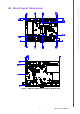
2.1 Jumpers & Switches
The MIO-5271 has a number of jumpers that allow you to configure your system to
suit your application. The table below lists the functions of the various jumpers.
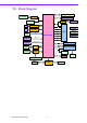
2.2 Connectors
Onboard connectors link the MIO-5271 to external devices such as hard disk drives,
a keyboard, or floppy drives. The table below lists the function of each of the board's
connectors.
Table 2.1: Jumpers & Switches
J2 Auto Power On Setting
J3 LCD Power
SW2 mPCIe & mSATA selection
SW3 Clear CMOS
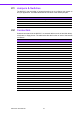
Table 2.2: Connectors
Label Function
CN1 12V Power Input
CN5 Power Switch
CN7 Reset
CN8 GPIO
CN9 VGA
CN10 HDMI/DisplayPort
CN11 SATA2
CN12 SATA1
CN13 SATA Power
CN14 Full-Size Mini PCIE w/ mSATA
CN15 SIM
CN16 External USB2.0+USB3.0
CN17 External USB2.0+USB3.0
CN18 COM1/COM2
CN19 COM3/COM4
CN21 Gigabit Ethernet 1 & 2
CN23 Audio
CN24 MIOe
CN25 Inverter Power Output
CN26 LVDS
CN29
SMBus/I
2
C
CN31 Half-Size Mini PCIE
FAN1 System FAN