
User manual
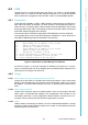
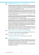

Table Of Contents
- UTCA-5503
- Contents
- 1 Board Specification
- 2 Applications and Overview
- 3 Mezzanine Module Options
- 4 Operations
- 5 Firmware Upgrades
- 6 Overview of Supported Features and Known Limitations
- A MCH Pin List, Connector 1
- B IPMI/PICMG Command Subset Supported by the MCMC
- C IPMI/PICMG Command Subset Supported by the Carrier Manager
- D IPMI/PICMG Command Subset Supported by the uShM

UTCA-5503 User Manual 34
5.1 MCMC Boot Process
Located at the beginning of the user memory space of the H8S processor is a small
software component called the boot loader, which has several important tasks to per-
form for the MCMC boot process. The MCMC firmware is also located at the user
memory space, right behind the boot loader. A second copy is held in external flash.
providing roll back features in case of failed FW upgrades.
The MCMC boot process will include the following steps:
1. The Boot Loader performs an early Power-On Self Test (POST) of the hard-
ware.
2. The Boot Loader calculates the checksum of the MCMC firmware image. If the
checksum is not valid, the Boot Loader sends a notification message to the
Serial Debug line and enters the upgrade mode.
3. The Boot Loader checks if the most recent reset was caused by a user upgrade
request received by the MCMC firmware from a serial interface. If so, the Boot
Loader sends a notification message to the Serial Debug line and enters the
upgrade mode.
4. Optionally, the Boot Loader polls the Serial Debug Interface for an amount of
time and if an ESC (ASCII 27) character is read from this interface before this
time elapses, the Boot Loader sends a notification message to the Serial Debug
line and enters the upgrade mode.
5. If the Boot Loader is in the normal (not upgrade mode), it passes control to the
MCMC firmware by calling its entry point.
The following self tests are performed in POST:
! H8S internal SRAM test (read/write)
! FPGA status and register access test
! External SRAM test
! FRU EEPROMs
! SDRs
! I2C device access
A failing FPGA test is a critical error of the aMCH. The MCMC will turn on the OOS
LED and try to re-program the FPGA from the recovery image programmed during
the manufacturing process. It will then trigger a board reset and try to restart.
5.2 MCMC Firmware Validation
In addition to the MCMC firmware being located in the user memory space in H8S, a
backup copy of the MCMC firmware is also stored in an external flash memory. As
mentioned in the previous section, the Boot Loader will perform a checksum opera-
tion to validate the MCMC firmware (in H8S) during boot up. If the checksum opera-
tion fails, the firmware image is judged as non-functional. The Boot Loader will then
restore the firmware from the backup copy.
Each time when the MCMC firmware is upgraded via the Boot Loader, a redundant
copy of the current firmware is saved in the external flash first followed by download-
ing and programming the new image to H8S. If the firmware upgrade is interrupted
(e.g. a power failure occurs) or the new firmware turns out to be corrupted, the Boot
Loader will also restore the backup image from the external flash.