
User manual

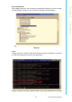
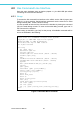
Table Of Contents
- UTCA-5503
- Contents
- 1 Board Specification
- 2 Applications and Overview
- 3 Mezzanine Module Options
- 4 Operations
- 5 Firmware Upgrades
- 6 Overview of Supported Features and Known Limitations
- A MCH Pin List, Connector 1
- B IPMI/PICMG Command Subset Supported by the MCMC
- C IPMI/PICMG Command Subset Supported by the Carrier Manager
- D IPMI/PICMG Command Subset Supported by the uShM

UTCA-5503 User Manual 22
4.1 Power the MCH
4.1.1 Preparation
UTCA-5503 requires an uTCA chassis with uTCA power supply for operation.
4.1.2 Insertion
Insert UTCA-5503 into a MCH slot (PCB1) on the backplane of an uTCA chassis.
The chassis can be powered or un-powered as the MCH supports hot swap. When
the system is powered and the handle switch is closed, the blue LED (LED0) will start
to give long blinks, and the FRU LED2 starts blinking green (FW is active) The blue
LED will turn off at the same time. In case of a failure, the red OOS LED will be lit and
the FW will constantly reboot, trying a successful startup. LED2 will not be lit on OOS
status.
Once the MCH has reached M4 and the payload is powered, LED2 will be perma-
nently lit. When management LAN is routed to the GbE switches, the payload will be
powered regardless of the FRU state.
The boot process can be observed through the serial debug interface (chapter 3.2.2).
4.1.3 Extraction
To remove the MCH from the backplane, pull the handle switch - the MCH will start
deactivation, and the LED0 will give short blue blinks. When the blue LED is con-
stantly lit, it is safe to extract the MCH.
Additionally LED2 will provide feedback about the payload power status.
4.2 Use Mini-USB Debug Interface
A PC and a USB cable (with regular Type-A plug and Mini-USB Type-A plug) are
needed to establish the communication with the MCH’s debug interface. The Mini-
USB jack allows connecting the H8S debug interface and the command line interface
as well as connectivity to PCB3.
4.2.1 Preparation
The Mini-USB debug interface utilizes a Silicon Laboratories CP2102 USB-to-UART
bridge. Drivers for Microsoft Windows, Linux, or Mac OS can be found at:
http://www.silabs.com/tgwWebApp/public/web_content/products/Microcontrollers/
USB/en/mcu_vcp.htm