
User manual
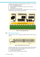
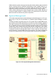

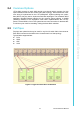


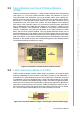
Table Of Contents
- UTCA-5503
- Contents
- 1 Board Specification
- 2 Applications and Overview
- 3 Mezzanine Module Options
- 4 Operations
- 5 Firmware Upgrades
- 6 Overview of Supported Features and Known Limitations
- A MCH Pin List, Connector 1
- B IPMI/PICMG Command Subset Supported by the MCMC
- C IPMI/PICMG Command Subset Supported by the Carrier Manager
- D IPMI/PICMG Command Subset Supported by the uShM
UTCA-5503 User Manual 18
3.5 Additional Fabric Extension Module (PCB4)
PCB4 also serves as a fabric extension module of PCB1. However, the actual dimen-
sions and limitations of the module will heavily depend on the PCB3 implementation.
So, PCB3 and PCB4 should always be considered as a common set.
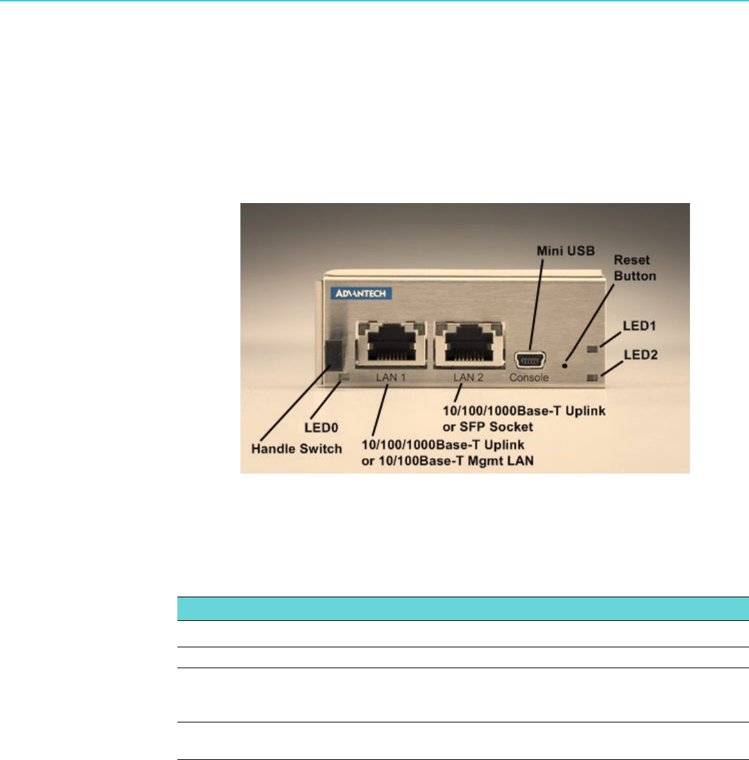
3.6 Front Panel Connectors and Indicators
Figure 3.4 UTCA-5503 Front Panel
3.6.1 MCMC LED Indicators
Although the uTCA specification still mandates four LEDs, UTCA-5503 implementa-
tion follows the latest AMC.0 specification.
3.6.2 Handle Switch
A handle switch is implemented to support the hot swap function of the MCMC. The
handle switch type and location are designed according to the MicroTCA base speci-
fication.
3.6.3 Mini USB
The USB port is used for debugging, diagnostic information and implementation of a
serial console interface.
3.6.4 Reset Button
The reset button at the front panel is used for resetting the MCMC.
Table 3.2: Front Panel MCMC LED’s
LED Color Description
0 Blue Hot swap indicator
1 Red Flashing = Bootloader active or update (FW/FPGA) running; applica-
tion temporarily out of service
Solid = OOS (error)
2 Green Flashing = FW application active (payload unpowered)
Solid = FW application active (payload powered)