
User manual
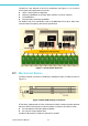
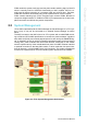

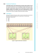


Table Of Contents
- UTCA-5503
- Contents
- 1 Board Specification
- 2 Applications and Overview
- 3 Mezzanine Module Options
- 4 Operations
- 5 Firmware Upgrades
- 6 Overview of Supported Features and Known Limitations
- A MCH Pin List, Connector 1
- B IPMI/PICMG Command Subset Supported by the MCMC
- C IPMI/PICMG Command Subset Supported by the Carrier Manager
- D IPMI/PICMG Command Subset Supported by the uShM
UTCA-5503 User Manual 16
As a modularized MCH base board (PCB1), UTCA-5503 can be completed with addi-
tional functionalities by integrating with mezzanine PCB’s such as PCB2, PCB3, and
PCB4. These PCB’s are mounted like a stack and share one common face plate.
This chapter will delve into more detail about the integration of these mezzanine
PCB’s with UTCA-5503.
3.1 PCB Levels and Stacking
Each level may have access to a backplane connector. This interface may be imple-
mented with a standard, AMC-style card edge connector or an MCH tongue (“plug”)
connector. The aMCH uses card edge connectors for PCB Levels 1 and 2 and plug
connectors for PCB Levels 3 and 4. The board-to-board interconnection is allowed
for the following PCB levels.
! PCB1 to PCB2
! PCB1 to PCB3
! PCB3 to PCB4
All PCBs of the aMCH need to implement a thickness of 1.6mm +/-10%. The maxi-
mum PCB outline is described in detail in the MicroTCA base specification including
the card edge and tongue connector details.
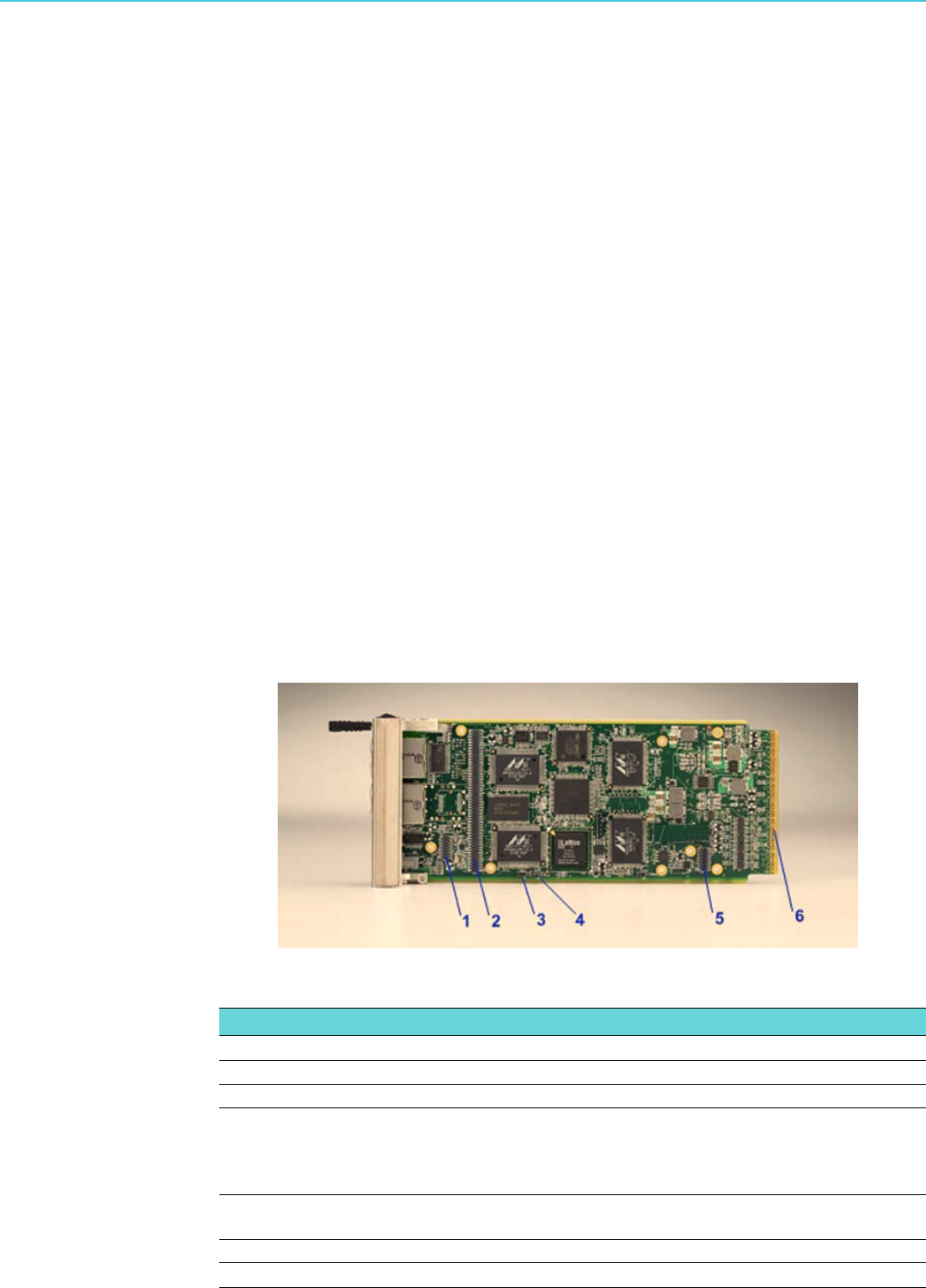
3.2 Base Module (PCB1)
As mentioned in the previous chapters, the aMCH base module carries, (1) an IPMI
controller for up to twelve AMC modules, Power and Cooling Units, backplane
devices, and front panel connectors, and (2) two GbE Layer2 switches for Fabric A
for up to twelve AMC modules, front panel uplink, and SGMII interface for the CPU/
L3 switch on PCB3. See Figure 3.1 and Table 3.1 for detailed description of the base
module.
Figure 3.1 Base Module PCB View
Table 3.1: Base Module Connection and Jump Headers
Silk Screen Description
1 CN8 Clock/Alarm module header (for future use)
2 CN5 PCB3 module header (for future use)
3 CN12 Mini USB debug console default mode after power up - it is possi-
ble to switch between both interfaces at runtime. Open = select
H8S serial debug interface. Closed = select H8S command line
interface
4 CN13 LAN1 routing control jumper. Open = routed to management LAN.
Closed = routed to GbE switches
5 CN9 PCB2 module header (for future use)
6 AMC card edge connector