
User manual
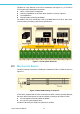
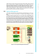

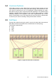

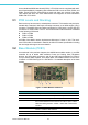
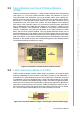
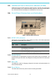
Table Of Contents
- UTCA-5503
- Contents
- 1 Board Specification
- 2 Applications and Overview
- 3 Mezzanine Module Options
- 4 Operations
- 5 Firmware Upgrades
- 6 Overview of Supported Features and Known Limitations
- A MCH Pin List, Connector 1
- B IPMI/PICMG Command Subset Supported by the MCMC
- C IPMI/PICMG Command Subset Supported by the Carrier Manager
- D IPMI/PICMG Command Subset Supported by the uShM

UTCA-5503 User Manual 10
The MCH is a key element of the uTCA architecture (see Figure 2.1). It is used in
uTCA systems and applications to provide
! carrier / shelf system management
! switching capabilities for the basic fabric interface (“common options”)
! clock distribution
! Fat pipes fabric switching capabilities
For details of the uTCA architecture, refer to PICMG® MicroTCA.0 R1.0, Micro Tele-
communications Computing Architecture specification.
Figure 2.1 uTCA System Elements
2.1 Mechanical Basics
The MCH consists of a stack of 4 PCB layers, labeled as PCB1 to PCB4 as shown in
Figure 2.2.
Figure 2.2 MCH PCB Naming Conventions
UTCA-5503, implemented on PCB1 of Advantech’s MCH, contains the basic features
that every MCH must support as well as interface connections to PCB2 to PCB4.
! the management controller called the MCMC
! the common options switch fabric
All other PCBs except for PCB1 are optional for an MCH.