
User manual


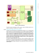
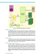

Table Of Contents
- UTCA-5503
- Contents
- 1 Board Specification
- 2 Applications and Overview
- 3 Mezzanine Module Options
- 4 Operations
- 5 Firmware Upgrades
- 6 Overview of Supported Features and Known Limitations
- A MCH Pin List, Connector 1
- B IPMI/PICMG Command Subset Supported by the MCMC
- C IPMI/PICMG Command Subset Supported by the Carrier Manager
- D IPMI/PICMG Command Subset Supported by the uShM

UTCA-5503 User Manual 6
Figure 1.2 GbE Switch Management and E-keying
1.2.4.2 Gigabit Ethernet PHYs
Two Marvell 88E1111 PHY’s are used. These PHY’s support two different MAC inter-
faces: SGMII and RGMII. The SGMII interface is connected to the GbE switch and
the RGMII interface will be connected to PCB3. Either selection of the two interfaces
can be configured manually though IPMI command by the user when PCB3 is
detected. This option is a static configuration that will not be changed during run time.
Each of the PHY’s is connected to a 10/100/1000BT copper interface. The use of a
2nd PHY is optional and mutual exclusive with the SFP port option (as shown in Fig-
ure 1.1).
1.2.4.3 SFP Port
A standard SFP port is provided as alternate assembly option instead of a 2nd RJ-45
connector. Standard SFP’s are supported. The SFP will be directly connected to the
GbE switch fiber port. To support auto configuration and management, the presence
detect signal from the SFP is connected to the FPGA.
1.2.4.4 Management LAN Controller
An SMSC LAN9115 10/100Mbit Ethernet controller is connected to the MCMC bus
interface to provide a management LAN interface. The LAN9115 contains an inte-
grated 10/100BT PHY which may be used on the 1st RJ45 on the front panel as dis-
cussed above. Alternatively, the LAN9115 supports a MII interface which is
connected to the GbE switch’s Reverse MII interface. This interface is provided as an
option to support routing management LAN traffic through the GbE switch fabric.
Note that the implementation for this option is through jumper setting. A selection
between the two options shall be a static configuration chosen at power up of the
module.