
User manual


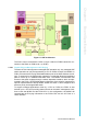
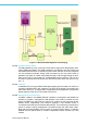

Table Of Contents
- UTCA-5503
- Contents
- 1 Board Specification
- 2 Applications and Overview
- 3 Mezzanine Module Options
- 4 Operations
- 5 Firmware Upgrades
- 6 Overview of Supported Features and Known Limitations
- A MCH Pin List, Connector 1
- B IPMI/PICMG Command Subset Supported by the MCMC
- C IPMI/PICMG Command Subset Supported by the Carrier Manager
- D IPMI/PICMG Command Subset Supported by the uShM
5 UTCA-5503 User Manual
Chapter 1 Board Specification
Figure 1.1 GbE architecture
The PHY’s may be connected to a CPU or Layer 3 switch on PCB3 instead of a con-
nection to the switch on PCB Level 1 (or PCB1).
1.2.4.1 Gigabit Ethernet Management and E-Keying
The basic UTCA-5503 supports unmanaged GbE operation only. Any managed GbE
switch operation can only be supported by a CPU on PCB3. However, the MCMC on
PCB1 will control the E-keying and disable/enable ports of the GbE switches accord-
ingly. To support this, the switches are operated in a mode that allows the backplane
ports to come up in a disabled state after reset. The MCMC microcontroller has
access to the switch registers through a switch dependent interface, which is imple-
mented in the FPGA. An EEPROM based configuration of the switch is supported for
optional implementations without MCMC where the switch is auto-configured and
acts as a purely unmanaged GbE switch.
To support managed applications driven by a CPU on PCB3, the FPGA is also
hooked up to a LPC bus providing shared access to the switch management inter-
face to both the MCMC and the PCB3 CPU. In this configuration, the MCMC will
communicate the E-keying information to the PCB3 CPU over the LPC Bus or a
UART interface.