
User manual

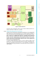

Table Of Contents
- UTCA-5503
- Contents
- 1 Board Specification
- 2 Applications and Overview
- 3 Mezzanine Module Options
- 4 Operations
- 5 Firmware Upgrades
- 6 Overview of Supported Features and Known Limitations
- A MCH Pin List, Connector 1
- B IPMI/PICMG Command Subset Supported by the MCMC
- C IPMI/PICMG Command Subset Supported by the Carrier Manager
- D IPMI/PICMG Command Subset Supported by the uShM

UTCA-5503 User Manual 4
1.2.1.3 MCH to MCH Communication
At the moment of this manual creation, MCH redundancy is not supported by PPS.
Consequently, to avoid potential damage, two MCH modules should not be used in
one system until a firmware update with the PPS MCH redundancy feature is made
available.
The two MCH’s are linked through a crossover communication channel which may
include any of the following interfaces:
! a crossover IPMB bus
! a full duplex crossover interface with differential I/O’s (Xover 0, 2)
! a half duplex crossover interface with differential I/O’s (Xover 1).
! a Fabric A update channel
While the later interface is for linking the fabric interfaces of the MCH’s, the other
three interfaces are for communication and redundancy & failure management. The
protocol on these interfaces is not available in the uTCA specification and is imple-
mentation specific.
1.2.1.4 Thermal Sensor
Two LM75 thermal sensors are placed on opposite sides and differing locations of
the PCB to monitor the ambient air temperature across PCB1 on UTCA-5503.
1.2.2 FPGA
An FPGA is used to integrate MCMC related glue logic, GPIOs, a UART and other
interfaces. It will also hook up to the optional LPC bus to the Fabric Extension Con-
nector (for a fabric extension module on PCB3). It may be used to connect FPGA
resources to an optional processor on PCB3. A Lattice LXFP6 device is used to
implement the FPGA.
1.2.3 RTC
The RTC is attached to the private I2C bus of the MCMC. It provides time of day and
calendar function for the MCMC.
1.2.4 Base Fabric/Gigabit Ethernet
The overall Ethernet implementation on UTCA-5503 can be illustrated by the follow-
ing diagram. Two Marvell 88E6185 switches are used to fulfill the following connec-
tions.
! 12 SERDES interface connections to AMCs on the uTCA backplane.
! 1 SERDES interface connection to the update channel of the other MCH on the
uTCA backplane.
! 1 SGMII interface to fabric modules on PCB3.
! 1 SGMII interface to a GbE PHY device that may drive a 10/100/1000BT inter-
face on the front panel. The RJ45 on the front panel may also be used to con-
nect to the management LAN interface of the MCMC.
! 1 SGMII interface to a GbE PHY device that may drive another 10/100/1000BT
interface or a SFP socket on the front panel.
! 1 Reverse MII interface for connection to the MCMC management LAN control-
ler.