SBM75e Series Modulator L-Band Satellite Modulator 32 k – 45 M Symbol BPSK/QPSK /8PSK/16APSK/32APSK Installation and Operation Manual Version 1.1 March 2009 Copyright © 2008 AdvantechAMT. All rights reserved. AP.TP-xxxx.
Preliminary Pages Preface Thank you for purchasing a Modulator from Advantech AMT. These products build on the success of the SL/QD series, the industry’s first L-band digital satellite modems. Advantech Advanced Microwave Technology is an international company specializing in the development of satellite communication systems.
Preliminary Pages Copyright Notice Copyright © 2004-2008 AdvantechAMT. All rights reserved. This manual may not be reproduced or disclosed in whole or in part by any means without the written consent of AdvantechAMT, Inc.
Preliminary Pages Warranty and Service Advantech AMT warrants to the Purchaser that the Products and any Repaired Products (Repairs) will be free from defects in material and workmanship for a period of two years from the date of shipment to the Purchaser. Advantech AMT’s obligation under this warranty is limited to replacing or repairing, at ADVANTECH AMT’s option, Products or Repairs found by Advantech AMT to be defective within the warranty period.
Preliminary Pages Safety Notices Radio Frequency (RF) Interference This equipment generates, uses and can radiate radio frequency energy, and, if not installed in accordance with the instructions contained herein, may cause interference to radio communications.
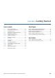
Preliminary Pages Contents Chapter 1 Getting Started Describes the function of the equipment and its purpose within the system. It also provides a guided tour of the base unit front and rear panel controls, indicators and connectors. Chapter 2 Installation Details the procedures for installing the equipment, including important safety information, details the base unit connectors and cables. Chapter 3 Front Panel Monitoring & Control Describes how to configure the unit using the front panel display.
CHAPTER 1: Getting Started List of Contents List of Figures 1.1 1.1.1 1.1.2 1.1.3 1.1.4 1.1.4.1 1.1.4.2 Scope of this Manual ............................................... 1-2 Who Should Use This Manual ................................... 1-2 Version Information ................................................... 1-2 Equipment Covered by this Manual ...................... 1-2 RF/IF Interface Options............................................. 1-2 Modulator L Band Output ..............................
Getting Started 1.1 Scope of this Manual 1.1.1 Who Should Use This Manual This manual is intended for operators/users of the SBM75e of Network L-Band and 70/140 MHz Satellite Modulators to assist in the installation, operation, fault-finding and maintenance of the equipment. Throughout this manual, this product is referred to as the ‘SBM75e Modulator ’. WARNING DO NOT REMOVE THE COVERS OF THIS EQUIPMENT. HAZARDOUS VOLTAGES ARE PRESENT WITHIN THIS EQUIPMENT AND MAY BE EXPOSED IF THE COVERS ARE REMOVED.
Getting Started 1.2 Summary of Features 1.2.1 Overview The SBM75e Modulator supports all the major satellite standards, both Intelsat and DVB, in a one rack unit chassis, if the appropriate options are enabled. Figure 1.1: SBM75e Modulator Block Diagram 1.3 Guided Tour 1.3.1 Enclosure The SBM75e Modulator can be fitted into a 1U high enclosure and may be used on a desktop or rack mounted. 1.3.
Getting Started Figure 1.2: SBM75e Modulator Front Panel 1.3.2.1 Vacuum Fluorescent Display (VFD) The VFD can display two lines of up to 40 characters each and has a wide viewing angle. 1.3.2.2 LED Indicators The LEDs on the front panel indicate the summary status of major Modulator conditions. LEDs that illuminate GREEN indicate that the function is in operation. LEDs that illuminate RED indicate a fault condition. Figure 1.3: Front Panel LED Indicators Table 1.1: SBM75e Front Panel LEDs 1.3.2.
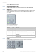
Getting Started Table 1.2: Front Panel Keypad Functions Keys Description ENTER This key will enter a submenu or enter an editing mode of a parameter. The Parameter is only set once ENTER is pressed again otherwise changes will not be saved. Commands such as reconfigure and reset will activate once the ENTER key is pressed. CLEAR This Key will return to the previous display or exit out of an editing mode without changing the parameter. ST These keys are used to navigate the menus.
Getting Started 1.3.3 Rear Panel Description The SBM75e Modulator rear panel provides a number of connectors Further details, including pinouts are described in Chapter 2, Installation AC Power Connector Redundancy Connector 1 PPS in Connector Ethernet Connector ON/OFF Switch M&C Modulator Connector Ext Ref in 70/140 MHz Connector Out connector ALARM Connector ASI 1/2/3/4 Connectors RS485 Connector L-Band out Connector Figure 1.
Getting Started 1.4 Typical System Setup The following diagram shows a typical system setup and signal interconnections. For detailed connector information, see Chapter 2, Installation. Figure 1.
Getting Started 1-8 SBM75e Series Modulator Installation and Operation Manual
CHAPTER 2: Installation List of Contents 2.6.6 2.6.7 2.6.8 2.6.9 2.6.10 RF (L-Band) Output Connector ............................. 2-12 ASI Input Connector ............................................... 2-12 1Pulse Per Second (1PPS) InputConnector ......... 2-12 External Reference Input Connector ................... 2-13 70/140 MHz (IF) Output Connector ...................... 2-13 2.7 Configuring the Modulator for Best Performance ............................................................
Installation 2.1 Introduction This chapter describes the unpacking, inspection and installation considerations. 2.1.1 Read This First! The SBM75e Modulator must be handled carefully and thoughtfully to prevent safety hazards and damage. Ensure the personnel designated to install the unit have the appropriate skills and knowledge. If in any doubt, contact Advantech AMT Customer Support. Follow the instructions for installation and only use installation accessories recommended by the manufacturers. 2.1.
Installation 2.2 Preliminary Checks 2.2.1 Mechanical Inspection When taking delivery of an SBM75e Modulator, check the equipment items delivered against the enclosed delivery note. Inspect the equipment for damage in transit. If in doubt, contact Customer Support (see Preliminary Pages). NOTE… Do not remove the covers of this equipment as doing so may invalidate any warranties, cause a safety hazard and/or affect the EMC performance. It may also invalidate any safety tests.
Installation 2.3.2 Inventory Take inventory of the complete package to ensure that all necessary parts are present. A quick review of your pre-installation site survey form, purchase order, and shipping list should reveal any discrepancies. The box should contain the modulator, a power cord, a fan filter kit, and this manual. If any additional kits have been ordered such as the Rear Support Kit verify the contents using the packing slip 2.
Installation Figure 2.1: Rack Mount Support Kit The left and right mounting kit supports are attached to the SBM75e Modulator with two #6-32 x 5/16” Phillips countersunk screws. Each angle is attached to a support by one #8-32 x ½” screw, one #8 lock washer, one#8 flat washer 3/8” OD, one #8 flat washer ½” OD and one #8-32 hexagonal nut. Do not use this product as a support for any other equipment. 2.4.
Installation 2. Do not install equipment so that the air intake of one aligns with the outlet on another. Provide baffles and adequate spacing. 3. The fans contained within this unit are not fitted with a dust/insect filter. Pay particular attention to the environment in which it is to be used. The unit is designed for stationary or fixed use only. Ensure it is firmly and safely located and has an adequate through-flow of air. Allow at least 50 mm free air-space at each side of the equipment.
Installation 2.5.2 AC Power AC power is supplied to the modulator via socket JP1 (IEC 320(M) on the rear panel. WARNING UNDER NO CIRCUMSTANCES SHOULD THE EARTHING PIN OF A 3-PIN PLUG BE REMOVED TO OPERATE WITH A 2-PIN SOCKET. Caution The SBM75e Series Modulators are shipped with a North American standard 3-pin power cable that is designed to work with 100-120V power supplies only.
Installation Table 2.2: Supply Cable Wiring Colours UK (BS 1363) EUROPE (CEE 7/7) USA (NEMA 5-15P) Earth: Green-and-yellow Green-and-yellow Green Neutral: Blue Blue White Live: Brown Brown Black If the colours do not correspond with the coloured markings identifying the terminals in a locally supplied plug, proceed as in Table 2.3 (included for reference). Table 2.3: Non Standard Supply Cord Wire Colours 2.5.2.
Installation 2.6 Signal Connections The majority of signal connectors are located on the rear panel of the SBM75e Modulator, except for one monitor and control connector located on the front panel. Note Always use the specified cables supplied for signal integrity and compliance with EMC requirements (see appendix A, Technical Specification). 2.6.
Installation 2.6.3 Item Specification Connector type: 9-way, D-type, Female Connector designation: M&C RS485 Standard: RS485 Configuration: DCE Pin-outs: 1 Signal Ground 6 Power Detector + 2 Power Detector 7 Not Used 3 Not Used 8 RS-485 Rx+ 4 RS-485 Tx+ 9 RS-485 Rx- 5 RS-485 Tx- 1 5 6 9 M&C Connector - 10/100BaseT Ethernet There are two 10/100BaseT Ethernet M&C ports on the rear panel.
Installation Item Specification Connector type: 9-way, D-sub type, Female Connector designation: ALARMS Standard: Custom Configuratio n: - Relay 1: Not Ued 1 Common 6 Normally Open 8 Normally Closed 2 Common 7 Normally Open 3 Normally Closed 5 Common 4 Normally open 9 Normally closed Relay 2: Modulator Relay 3: Not Used 2.6.5 1 5 9 6 Redundancy This is an optional feature, although the connector appears on the rear panel (REDUNDANCY, a 15-pin D-sub female).
Installation 2.6.6 RF (L-Band) Output Connector The connector labelled as L-Band OUT transmits RF signals to the antenna. For signal specification, see Appendix A: Technical Specification. Table 2.9: RF (L-Band) Output Connector 2.6.7 Item Specification Connector type: F-type 50 Ω female socket Connector designation: L-BAND OUTPUT Pin-outs: Centre RF Signal Shield Ground/Chassis ASI Input Connector One or more ASI inputs may be provided on the rear panel, labelled as ASI 1, ASI 2, etc.
Installation Table 2.11: 1PPS Input Connector 2.6.9 Item Specification Connector type: BNC 50 Ω socket Connector designation: 1PPS IN Pin-outs: Centre Video Signal Shield Ground/Chassis External Reference Input Connector One connector is provided to receive an external reference signal. For signal specification, see Appendix A: Technical Specification. Table 2.12: Ext Ref In Connector 2.6.
Installation BUC power is off (bucpower off) 10 MHz reference is off (tfref off) 3. Set modulator power to -25 dBm (tlevel -25) 4. If required and if the option is fitted, turn on DC power to BUC (bucpower on). 5. If required and if the option is fitted, turn on 10 MHz reference to the BUC (tfref on). 6. Increase modulator output power to desired level (tlevel < desired level >).
Installation Note The DVB system can be configured to transmit both MPEG-2 and non MPEG-2 data. When using DVB modes to transmit non MPEG-2 data it is necessary to turn DVB REMOVE MARK ON in the modulator (command RRMVMK ON). This is required, since DVB FEC utilizes the MPEG framing structure, which must therefore be imposed by the modulator (and similarly removed by the modulator). There is a performance overhead associated with the sync byte, but it is only 0.5% of data rate. Table 2.
Installation With the receiver algorithms taken into consideration, carrier synchronization can be achieved in presence of phase noise of existing outdoor equipment, including the LNB and worst-case thermal noise for any DVB-S2 mode. Some of the transmission modes, such as for example 8PSK rate 3/5 and rate 2/3, 16APSK rate 3/4 and 32APSK 4/5 required the use of pilot symbols to avoid cycle slips. For ACM operation, the use of pilot symbols can guarantee continuous receiver synchronization.
CHAPTER 3: Front Panel Monitoring & Control List of Contents List of Tables 3.1 Introduction ............................................................... 3-2 3.2 Powering up the Modulator .................................... 3-3 3.3 3.3.1 3.3.2 3.3.2.1 3.3.2.2 3.3.2.3 3.3.2.3.1 3.3.2.3.2 3.3.2.4 3.3.2.5 3.3.2.5.1 3.3.2.5.2 3.3.2.5.3 3.3.2.5.4 3.3.2.5.5 3.3.2.5.6 3.3.2.5.7 3.3.2.5.8 3.3.2.5.9 3.3.2.5.10 3.3.2.5.11 3.3.2.5.12 3.3.2.5.13 3.3.2.5.14 3.3.2.5.15 3.3.2.5.16 3.3.2.6 3.3.2.7 3.3.2.8 3.3.
Front Panel Monitoring & Control 3.1 Introduction The SBM75e Modulator is equipped with an active front panel (LCD screen and keypad) which provides an easy way to setup the Modulator without the need for a PC or generic control system. This chapter is intended to allow maintenance personnel or users to quickly set up the Modulator for initial use. Switch On Advantech AMTTM SBM-75 Overview: Press any key to continue..... Overview : (para. 3.3.1) Select Board > (para. 3.3.2) Chassis Info > (para. 3.3.
Front Panel Monitoring & Control 3.2 Powering up the Modulator When power is applied to the Modulator (in accordance with the instructions given in Chapter 2, Installation), approximately 90 seconds should be allowed for the system to boot-up, complete internal checks, allow the internal crystal oven to reach operating temperature and the frequency of the crystal to stabilize. The following screen is then displayed: Advantech AMTTM SBM-75 Press any key to continue..... 3.
Front Panel Monitoring & Control 3.3.2.1 Menu Item Operations Card Information > Reports card information such as feature keys and software version Status > Lists the status of the input and configuration. All parameters in this menu are read only. Configure > Allows configuration of various parameters within the unit.
Front Panel Monitoring & Control Menu Item 3.3.2.3 Operations Overflow : This will report OK or FIFO FULL Sync : This will report the input is synchronised Rate Measure : This will report the incoming bit rate in Kbit/s Rate Limit : This will report on the status of the rate limiter which will state either “Not Enabled”, “Rate Exceeded” or OK Configure All options selected within this menu are pending settings and will not take effect until the unit is reconfigured.
Front Panel Monitoring & Control MUX_A: MUX_B: Note The down arrow indicates that there are more profiles available. 10 profiles are currently supported. 3. Select the required profile. The following warning screen is displayed. Loading Profile: MUX_A ENTER = Confirm : CLEAR = Cancel The new configuration will be pending until the unit is reconfigured. To create and save a new profile: 1. Select the Create Profile option from the Profiles sub-menu. The following screen is displayed.
Front Panel Monitoring & Control 3.3.2.3.2 Coding When Coding is selected then the coding type is highlighted. By using the up and down arrows this coding type can be altered. The options are dependant upon the feature keys installed but the possible list is detailed in Table 3.9. Table 3.6: Coding Types.
Front Panel Monitoring & Control Menu Item Operations -> Data Rate: [199000000 BPS] Input : This entry does not appear in ACM mode. This allows the selection of the source of the input. The options are OFF, ASI1, ASI2, ASI3, ASI4, PRBS. The number of ASI is dependant upon unit configuration. Redundant Input : This entry does not appear in ACM mode. This allows the selection of the source of the input. The options are OFF, ASI1, ASI2, ASI3, ASI4, PRBS.
Front Panel Monitoring & Control Menu Item Operations be removed within the demodulator. In DVBS2 the data is transmitted without modification and no sync detection is performed. The data will be transmitted as Generic Stream Continuous. Reset Input on Error : This is only valid when the input type is selected to VBR, when ON then the unit will reset when the input is removed otherwise it will transmit null packets until the input returns.
Front Panel Monitoring & Control Table 3.8: Stream X Sub-menu Menu Item Operations Input: The selection can be off, PRBS, ASI X for stream X, ASI 1, ASI X L2 and ASI 1 L2. Setting Off will prevent any transmission of that stream. Setting PRBS will output a random stream and the rate will be set by cut off rate if the rate limit is set otherwise the PRBS will fill all available bandwidth. Redundant Input: The input is selected from off or ASI N where N is the redundant ASI pair e.g.
Front Panel Monitoring & Control 3.3.2.4 Settings This option allows setting of output parameters. These parameters may be viewed by selecting the Output option from the Select Board sub-menu. The parameters available are displayed in the following Table 3.12. Table 3.9: Output Sub-menu 3.3.2.5 Menu Item Operations Output power: Set the output power in dBm. Output Enable: Enable the output, this is selectable between ON and OFF CW Mode: To enable Continuous Wave Test Mode set to ON Ref.
Front Panel Monitoring & Control Property PMT info Status Description None The block cipher is not engaged Too many PMT(s) too many PMT(s) are received for the playout RAM (overflow) Incorrect PMT(s) A PMT cannot be modified to add/remove BISS SI (PIDs listed in the PMT would not be ciphered/deciphered) Missing PMT(s) A PMT listed in the PAT could not be retrieved OK All is OK 3.3.2.5.2 Configure 3.3.2.5.
Front Panel Monitoring & Control 3.3.2.5.8 Odd/Even-1 This mode is not part of the BISS standard but has been successfully interoperated with other manufacturers who have similar variants. Each MPEG packet has a field in the header which indicates if it is in the clear, encrypted using an ODD key or encrypted using an even key. While BISS only uses the one key, this mode allows two independent keys.
Front Panel Monitoring & Control 3.3.2.5.16 Configure BISS Use this configure to activate all the BIS settings. All settings will be stored and reused after a power-cycle. These values will not be stored in the profiles as keys can not be stored, they must be manually re-entered. 3.3.2.6 Reboot card The card is rebooted. This will be required after a software upgrade and will not effect other cards within the chassis. 3.3.2.7 Reset to factory defaults The card is reset to the factory default mode 3.
Front Panel Monitoring & Control SBM75e Series Modulator Installation and Operation Manual 3-15
CHAPTER 4: Web List of Contents 4.1 Introduction ............................................................... 4-3 4.2 4.2.1 Requirements for Accessing the GUI ..................... 4-3 Accessing the GUI .................................................... 4-3 4.3 4.3.1 4.3.2 4.3.3 Overview .................................................................... 4-4 Overview: Information.............................................. 4-4 Overview: Alarms ..................................................
Web GUI Monitoring & Control 4.8.3 4.8.4 4.8.5 4.8.6 4.8.7 4.8.8 4.8.9 4.8.10 4.8.11 4.8.12 4.8.13 BISS-0 ......................................................................... 4-24 BISS-1 ......................................................................... 4-24 BISS-E ......................................................................... 4-25 Odd/Even-1 ............................................................. 4-25 Odd/Even-E .............................................................
Web GUI Monitoring & Control 4.1 Introduction This chapter is provided to guide the user through the functions of the Graphical User Interface (GUI). Following the information given for accessing the GUI, those web pages which deal specifically with chassis functions will be described. Subsequent sections focus specifically on the operation of the SBM-75 in DVB-S2 modes. 4.
Web GUI Monitoring & Control Figure 4.1: SBM-75 Login Window 2. Enter the default Username: sbt 75 and the default Password: sbt 75. The entry level screen is displayed. The alarm status of the chassis and each installed functional unit is shown in the monitor bar on the left-hand side of the window. Note If a green tick is displayed in the ‘Overview’ tab of the monitor bar, this indicates that all equipment is working correctly. 4.3 Overview 4.3.
Web GUI Monitoring & Control 4.3.2 Overview: Alarms The alarm status of the units displayed in Figure 4.2 may be viewed by selecting the Alarms tab. A window similar to the one shown in Figure 4.3 is displayed. Figure 4.3: Alarms and Warnings Monitoring Window In this window each of the properties listed may be monitored on two levels - alarm or warning. The thresholds of some of these properties are adjustable by the user. The Status column shows that the ‘Fan Fault’ alarm status is satisfactory i.e.
Web GUI Monitoring & Control Figure 4.4: Changing Alarm Monitoring Window Additional information has now appeared in the ‘Status’ column, indicating that the ‘Fan too fast’ alarm is clear (shown by the green tick), and that the ‘Fan too fast’ warning has been asserted (shown by the yellow cross). The ‘Overview’ tab in the monitor bar on the left of the main panel now reflects this new warning state (shown by a yellow cross and a yellow fan symbol). 4.3.
Web GUI Monitoring & Control Figure 4.5: Status Window 4.4 SBM-75: Information The following web page menus are provided to enable the user to view and change the various properties of the SBM-75 functional unit. 4.4.1 Information By selecting the SBM-75 tab from the monitor bar on the left-hand side of the main panel, the user is able to set the name of the unit, check the software version and available optional features or capture a system snapshot.
Web GUI Monitoring & Control Figure 4.6: SBM-75 Management Window 4.4.1.1 Setting the Unit Name The default name of the functional unit is SBM-75. The name of the unit may be changed by entering the desired name in the ‘Name’ box and selecting the ‘Update’ tab. The new name should appear in the monitor bar on the left-hand side of the main panel as shown in the example in Figure 4.7. Figure 4.7: Setting the Unit Name Window 4.4.1.2 Version The relevant software version number is shown in this window.
Web GUI Monitoring & Control 4.4.1.4 Supported Features A list of optional features supported by the unit is shown below the MAC address and is detailed in Table 4.1. Table 4.1: Optional Supported Features 4.4.1.5 Feature Operations DVB-s If the text ‘DVB-S’ is displayed, this indicates that the SBM-75 is able to operate in DVB-S mode. DVB-S (QPSK, 8PSK) If the text ‘DVB-S (QPSK, 8PSK)’ is displayed, this indicates that the SBM75 is able to operate in this mode.
Web GUI Monitoring & Control Figure 4.8: SBM-75 Status Window This page will give a summary of the unit status. 4.5.1 Status monitoring Table 4.2: Status monitoring values FPGA Self Test Input Output Power Programmed Baud Rate Actual Baud Rate Board Temperature Core1 Temperature Clock Source Ext Clock Source Ref.
Web GUI Monitoring & Control 4.6 SBM-75: Alarms From the ‘Alarms’ window the user may configure alarms and/or warnings based on the behaviour and status of the modulator. Warnings are displayed to the user while alarms initiate the alarm relay. Alarms or warnings may be viewed by selecting the Alarms tab on the window shown above. A window, similar to that shown in Figure 4.9 is displayed. 4.6.1 Setting Alarms To set an alarm: 1.
Web GUI Monitoring & Control Figure 4.9: Alarms and Warnings Monitoring Window 4.6.3 General The following paragraphs detail the general alarms shown in Figure 4.9. 4.6.3.1 Lock State This property allows an alarm or warning to be raised if the modulator is unlocked. 4.6.3.2 FPGA Loading Failed This property allows an alarm or warning to be raised if one or more of the FPGA devices in the modulator fail to configure correctly. 4.6.3.
Web GUI Monitoring & Control 4.6.3.8 Output power out of specification This property allows an alarm or warning to be raised if the output power level is outside the calibration range. 4.6.4 Advanced Alarms The alarm/warning properties of the 1:1 redundancy unit may be viewed by selecting the Advanced alarm tab. A window, similar to that shown in Figure 4.10 is displayed. Figure 4.10: Output Alarms Window 4.6.4.
Web GUI Monitoring & Control 4.6.4.7 NTP Time error An alarm or warning will be generated when the returned time from the NTP server does not match the internal Time. 4.6.4.8 NCR not detected An alarm or warning will be generated when the programmed NCR is not detected. 4.6.4.9 NCR 1pps not detected An alarm or warning will be generated if the 1PPS is not detected. 4.6.
Web GUI Monitoring & Control Figure 4.11: Configuration Main Window 4.7.2 Input Data Type This is the method of locking to the incoming data. 4.7.2.1 VBR Variable bit rate mode will add Mpeg Null packets to guarantee a fixed symbol rate. The data rate has to be set to SPS, not BPS. The PCR values are re-stamped to meet the PCR jitter requirements. The reset on error tick box is only valid in this mode.
Web GUI Monitoring & Control 4.7.3 Input Type The input is selected from off, PRBS, ASI1,…,ASIX where X is the number of ASI inputs for the modulator. If PRBS is selected then a Pseudo Random Bit Stream will be generated, if the input type is normal then this pattern will be MPEG framed and transmitted as a Transport Stream. If unframed is selected then it will be transmitted as Generic Stream Continuous. 4.7.
Web GUI Monitoring & Control 4.7.6.1 Input The selection can be off, PRBS, ASI X for stream X, ASI 1, ASI X L2 and ASI 1 L2. Setting Off will prevent any transmission of that stream. Setting PRBS will output a random stream and the rate will be set by cut off rate if the rate limit is set otherwise the PRBS will fill all available bandwidth. 4.7.6.2 Redundant Input The input is selected from off or ASI N where N is the redundant ASI pair e.g. for stream 1 the redundant input would be ASI 2.
Web GUI Monitoring & Control 4.7.7 Profiles This option allows the user to save and recall a variety of operational profiles and exchange profiles between different chassis via a host computer. To make use of this option the Profiles tab may be selected from the main configuration window. A window, similar to that shown in Figure 4.12 is displayed. Figure 4.13: Profiles Main Window 4.7.7.
Web GUI Monitoring & Control Figure 4.14: Saving a New Profile To overwrite an existing profile: 4.7.7.2 1. Select the profile to be overwritten from the main Profiles window. 2. Enter a new profile name (e.g. MuxA) in the adjacent text box. 3. Select ‘Save’. Loading Existing Profiles To load an existing named profile: 1. Select the profile to be loaded from the main Profiles window. A window similar to that shown in Figure 4.14 is displayed. 2. Select ‘Load’. 3.
Web GUI Monitoring & Control Figure 4.15: Loading an Existing Profile 4.7.7.3 Downloading a Profile Occasionally it is necessary to clone a profile, or a set of profiles, amongst a family of units. To clone a profile: 1. Select the profile to be cloned from the profiles main window. A window similar to that shown in Figure 4.15 is displayed. Figure 4.
Web GUI Monitoring & Control 2. Select the Download link. A window similar to that shown in Figure 4.16 is displayed. Figure 4.17: Downloaded Profiles List 3. 4.7.7.4 Select all displayed files and save to a network file. Uploading a Profile Uploading is essentially the second stage in cloning a profile. To upload a profile: 1. Select the ‘Browse’ button. A window similar to that shown in Figure 4.17 is displayed. Figure 4.18: Choose file Window 2.
Web GUI Monitoring & Control 4.7.7.5 Factory Defaults This is a special profile which cannot be deleted or modified. 4.7.8 Settings The output levels of the SBM-75 may be viewed and set by selecting the Output Tab from the main Configuration window. A screen similar to that shown in Figure 4.18 below is displayed. Figure 4.19: Output Window 4.7.8.1 Output Power The output power may be set by entering the required level in dBm and selecting Set.
Web GUI Monitoring & Control 4.7.8.5 Internal Ref. Source The Internal timing can either be free running or aligned to a stored frequency which was derived from an external reference and then stored via the store frequency button. 4.8 BISS Encryption Basic Interoperable Scrambling System (BISS) is a satellite signal scrambling system developed by the European Broadcasting Union and a consortium of hardware manufacturers.
Web GUI Monitoring & Control Figure 4.20: BISS Window 4.8.1 BISS Mode Selection The options for the BISS mode are Off, Mode-0, Mode-1, Mode-E, Odd/Even-1, Odd/Even-E, User1 and User-E. Depending upon the selection, the available options will change within this section of the window. Figure 4.21: BISS Mode Selection Window Note All session words, injected ID and Encrypted session words cannot be read back and are not echoed back to the display.
Web GUI Monitoring & Control 4.8.5 BISS-E The transport stream is encrypted by a calculated session word. This session word is generated from an injected ID and an Encrypted session word. This is fundamentally more secure as both the Injected ID and Encrypted session words are required for decryption and each receiver could have a unique Encrypted session word. The Injected ID is a 14 digit Hex value and the Encrypted Session Word (ESW) is a 16 digit hex value.
Web GUI Monitoring & Control 4.8.9 User-E This is identical to the User-1 mode except a 16 digit hex value is required for the ESW and a 14 digit hex value is required for the injected ID. The even key is the same key as used for BISS-E. 4.8.10 BISS Insertion Period This sets the frequency that the Program Association Table (PAT), Programme Map Table (PMT) and Conditional Access Table (CAT) will be inserted into the stream. The default is 200 ms and this value should be suitable in most circumstances.
Web GUI Monitoring & Control 4.8.13 Encrypted Session Word Generator The Encrypted Session Word generator is an application which runs locally on the web browser and requires no network access. Consequently, the generated keys will have to be manually programmed into the unit via the front panel, GUI, SNMP or CLI. A 12 digit Hex value is entered in the Clear Session Word field and a 14 digit hex value is entered in the injected ID field. Clicking on the Generate ESW Key will produce a 16 digit hex value.
Web GUI Monitoring & Control 4-28 SBM75e Series Modulator Installation and Operation Manual
APPENDIX A: Technical Specification List of Contents List of Tables A.1 Introduction ............................................................... A-2 Table A.1: Technical Specification ............................................ A-2 A.2 Technical Specification ........................................... A-2 A.3 Standards Compliance............................................
Technical Specification A.1 Introduction This chapter details the technical specification and the standards with which it is compliant. A.2 Technical Specification The following table details the technical specification. Table A.
Technical Specification Description Specification 470 kbps to 200 Mbps DVB-S2 SHORT and NORMAL FEC Block 3 4 5 8 SHORT Block 16kbit /4, /5, /6, /9 3 4 5 8 9 NORMAL Block 64kbit /4, /5, /6, /9, /10 Modulation Type & FEC Rate QPSK : DVB 1/2, 2/3, 3/4, 5/6, 7/8 with RS (204,188), Optional 8PSK: DVB-DSNG PTCM Rate 2/3, 5/6, 8/9 with RS(204,188), Optional 16QAM, Optional: DVB-DSNG PTCM Rate 3/4, 7/8 with RS(204,188) code Modulation Roll-Off Factor 12% to 35% with 1% resolution Configurable Forward Error C
Technical Specification Description Specification Temperature: 0°C to 45°C (32°F to 122°F) RH: up to 90% non-condensing Altitude: Up to 3,045 m (10,000 ft) Storage / Transit: Temperature: -25°C to 85°C (-13°F to 185°F) RH: up to 95% non-condensing Altitude: Up to 12,180 m (40,000 ft) A.3 Standards Compliance The AMT-70 modem is compliant to the following Telecommunication Interface Standards: IEEE RS-422 / RS-449 / RS-530 and CCITT/ITU V.
Technical Specification SBM75e Series Modulator Installation and Operation Manual A-5
APPENDIX B: Glossary List of Contents B.1 Introduction ............................................................... B-2 B.2 Abbreviations and Technical Terms ....................... B-2 SBM75e Series Modulator Installation and Operation Manual List of Tables Table B.1: Glossary ........................................................................
Glossary B.1 Introduction This appendix provides a brief explaination of the abbreviations and technical terms used in this manual B.2 Abbreviations and Technical Terms The following table details the glossary. Table B.1: Glossary B-2 Term Description 16-QAM 16 Quadrature Amplitude Modulation: A modulation scheme used for the transmission of digital data, which modifies the amplitude and phase of an RF sinusoidal carrier frequency to represent data symbols.
Glossary Term Description BPSK Binary Phase Shift Keying: A modulation technique used to communicate data over long distances by altering the phase of a carrier signal according to the data binary states. The simplest form of phase shift keying, it uses two phases which are separated by 180° and so can also be termed 2-PSK. Sometimes called PRK, Phase Reversal Keying.
Glossary B-4 Term Description Decoder A unit containing the electronic circuitry necessary to decode encrypted signals. Some Decoders are separate from the receiver but in satellite TV broadcasting, the term is often used interchangeably as a name for an Integrated Receiver Decoder (IRD). The term IRD, or IRD / Decoder, is usually associated with satellite TV broadcasting while Cable systems are based on Converters or on Set-Top Boxes / Converters.
Glossary Term Description Earth Technical Earth: A connection that ensures all equipment chassis within a rack are at the same potential (“commoned”), usually by connecting a wire between the technical earth terminal and a suitable point on the rack. Also called a Functional Earth.
Glossary B-6 Term Description GUI Graphical User Interface: The use of pictures rather than just words to represent the input and output of a program. A program with a GUI runs under a windowing system and has a screen interface capable of displaying graphics in the form of icons, drop-down menus and a movable pointer. The on-screen information is usually controlled / manipulated by a mouse or keyboard.
Glossary Term Description JPEG Joint Photographic Experts Group: ISO/ITU standard for compressing still images. It has a high compression capability. Using discrete cosine transform, it provides user specified compression ratios up to around 100:1 (there is a trade-off between image quality and file size). kbit/s 1000 bits per second. Kbit 1024 bits, usually refers to memory capacity or allocation. Ku-band ITU-defined frequency range from 12 GHz to 18 GHz.
Glossary Term Description Mbit/s Million bits per second. MCPC Multiple Channels Per Carrier. MIB Management Information Base: A type of database used to manage the devices in a communications network. It comprises a collection of objects in a (virtual) database used to manage entities (such as routers and switches) in a network. MP@ML Main Profile at Main Level: A subset of the MPEG-2 standard, which supports digital video storage (DVD etc.) and transmissions up to 15 Mbit/s over various mediums.
Glossary Term Description OQPSK Offset Quadrature Phase Shift Keying: A variant of phase-shift keying modulation using 4 different values of the phase to transmit. It is sometimes called Staggered quadrature phase-shift keying (SQPSK). OSD On-screen display: Messages and graphics, typically originating from the SMS, and displayed on the subscriber’s TV screen by the IRD, to inform the subscriber of problems or instruct the subscriber to contact the SMS.
Glossary B-10 Term Description QPSK Quadrature Phase Shift Keying: A modulation technique used to communicate data over long distances by altering the phase of a carrier signal according to the four data states. Sometimes known as quaternary or quadriphase PSK, 4-PSK, or 4-QAM. RF Radio Frequency. RS Reed-Solomon coding: An error detection and correction, coding system.
Glossary Term Description Spectral Scrambling A process (in digital transmission) used to combine a digital signal with a pseudo-random sequence, producing a randomised digital signal that conveys the original information in a form optimised for a broadcast channel. TCP / IP Transmission Control Protocol/Internet Protocol: A set of communications protocols used to connect different computers over networks (in particular the internet).
Glossary B-12 SBM75e Series Modulator Installation and Operation Manual