IPPC-4001 Series 5.
Copyright This document is copyrighted, 2009, by Advantech Co., Ltd. All rights are reserved. Advantech Co., Ltd. reserves the right to make improvements to the products described in this manual at any time without notice. No part of this manual may be reproduced, copied, translated or transmitted in any form or by any means without the prior written permission of Advantech Co., Ltd. Information provided in this manual is intended to be accurate and reliable. However, Advantech Co., Ltd.
FCC Class A Note: This equipment has been tested and found to comply with the limits for a Class A digital device, pursuant to part 15 of the FCC Rules. These limits are designed to provide reasonable protection against harmful interference when the equipment is operated in a commercial environment. This equipment generates, uses, and can radiate radio frequency energy and, if not installed and used in accordance with the instruction manual, may cause harmful interference to radio communications.
Safety Instructions 1. Read these safety instructions carefully. 2. Keep this User's Manual for later reference. 3. Disconnect this equipment from any AC outlet before cleaning. Use a damp cloth. Do not use liquid or spray detergents for cleaning. 4. For plug-in equipment, the power outlet socket must be located near the equipment and must be easily accessible. 5. Keep this equipment away from humidity. 6. Put this equipment on a reliable surface during installation.
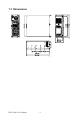
Contents Chapter Chapter 1 General Information ....................................... 2 1.1 1.2 Introduction ....................................................................... 2 Specifications .................................................................... 2 1.3 1.4 1.5 IPPC-4001 Series List ....................................................... 4 Dimensions........................................................................ 4 Exploded Diagram............................................
IPPC-4001 User Manual vi
CHAPTER 1 General Information 1 Chapter 1
Chapter 1 General Information 1.1 Introduction The IPPC-4001 is a 4U height 14-slot rackmount IPC workstation with 5.7" LCD display and built-in slim keyboard and Touch Pad drawer. It is designed as an all-in-one and cost-effective solution for traditional IPC users.
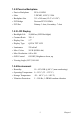
1.2.2 Passive Backplane • Passive Backplane PCA-6114P10 • Slots 2 PICMG, 10 PCI, 2 ISA • Backplane Size 315 x 260 mm (12.4" x 10.24") • PCI Bridge Pericom PI7C8150MA • PCI Slot Primary 3 slots, Secondary: 7 slots 1.2.3 LCD Display • Backlight Life 50,000 hrs (LED Backlight) • Contrast Ratio 300 : 1 • Display Size 5.7" • Display Type QVGA TFT LCD • Luminance 220 cd/m2 • Max. Colors 262 K (RGB 6-bit) • Max.
1.
CHAPTER 2 System Setup 5 Chapter 2
Chapter 2 System Setup 2.1 System Installation WARNING: Before starting the installation process, be sure to shut down all power from the chassis. Do this by turning off the power switch, and unplugging the power cord from the power outlet. When in doubt, consult with an experienced technician. 2.1.1 Attaching the Handles The handles for the front panel are in the accessory box. To install the handles, simply secure them to the front panel with the provided screws. 2.1.
System Reset 1: Press this switch to reinitialize the system. This is the same as the hardware reset button. (Default setting) System Reset 2: Press this switch to reinitialize the second system. (Optional) Alarm Reset Switch: Press this switch to suppress or stop an audible alarm. Whenever a fault in the system occurs (e.g. fan failure, rising chassis temperature, backplane voltage problem), an audible alarm is activated. Pressing this switch will cause the alarm to stop.
2.1.4 Drive Bay Installation The drive bay of IPPC-4001 can hold 5.25" (x3) devices. Installation of disk drives: 1. Remove the top cover 2. Undo the two screws of cushion and four screws on the drive bay 3. Lift off the Standard Drive Bay. 4. Insert the drives into their proper locations in the drive bay and secure them with the screws provided. 5. Connect the disk drive power and signal cables. 2.2 LED Indicators 2.2.
2.2.2 Power Status LED Power Status LED indicates the status of the backplane voltage signals. When a LED fails to light, it indicates a problem with one of the voltage signals. An audible alarm is sounded. Check to make sure that the power supply connector is properly attached to the backplane. If problem persists, consult an experienced technician. 2.3 Power Supply IPPC-4001 supports PS/2 and redundant power supply both and without any modifications.
2.4 Cooling Fan & Filter There are two cooling fans located inside the chassis. When one cooling fan breaks down, the system sounds a continuous alarm. To disable the alarm, press the Alarm Reset switch and replace the fan immediately. To replace a defective fan, refer to the figures below. Press location A and then pull B, the connector can then be released. If the filter is blocked with dust, refer to the figure below for the filter replacement procedure.
CHAPTER 3 Alarm Board 11 Chapter 3
Chapter 3 Alarm Board The alarm board is located under the cooling fan section. It gives an audible alarm when: 1. Any power supply module of redundant power supply fails 2. One of the cooling fans fai1s 3. Temperature inside the chassis rises 4. A problem occurs in one of the backplane voltage levels The detailed layout and specification of the alarm board are as follows: 3.
3.2 Alarm Board Specification Input Power: +5V, +12V Input Signals: • 7 FAN connectors (GND_+12V_FAN) • One thermal board connector (up to 8 thermal boards in a roll) • One power good input • One alarm reset input. • One voltage signal connector (connect from backplane, includes ±12V, ±5V, 3.
Pin Definition CN1 : External Power Connector, standard mini 4 Pin power connector Pin 1 : +12V, 2A current maximum Pin 2 : GND Pin 3 : GND Pin 4 : +5V, 2A current maximum CN2 : 10/100M LAN Connector Pin 1 : SPLED TERMPLANE Pin 3 : RX+ Pin 2 : Pin 4 : RX- Pin 5 : GND Pin 7 : TX+ Pin 9 : LILED Pin 11 : N/A Pin 6 : LVCC Pin 8 : TXPin 10 : TERMPLANE Pin 12 : NC CN4 : I2C Sensor board (LM75) Connector Pin 1 : +5V Pin 2 : Sensor board I2C bus clock Pin 3 : Sensor board I2C bus data Pin 4 : GND CN8 : RS-232 C
CN11 : SNMP-1000 Daughter Board Connector (Left side) Pin 1 : SIN Pin 2 : SOUT Pin 3 : CTS# Pin 4 : DCD# Pin 5 : RTS# Pin 6 : DTR# Pin 8 : ID 0 Pin 7 : DSR# Pin 9 : ATX ON Pin 10 : DO 4 Pin 11 : GND Pin 12 : DO 3 Pin 13 : Watchdog IN Pin 14 : DO 2 Pin 15 : Watchdog OUT Pin 16 : DO 1 Pin 17 : SPLED Pin 18 : NC Pin 19 : LILED Pin 20 : NC Pin 22 : NC Pin 21 : GND Pin 23 : TX+ Pin 24 : NC Pin 25 : TXPin 26 : NC Pin 28 : NC Pin 27 : RX+ Pin 30 : NC Pin 29 : RXPin 31 : TERMPLANE Pin 32 : NC CN12 : SNMP-1000 Daug
CN13 : Voltage Detect Input Connector Pin 1 : 5VSB Pin 2 : GND Pin 3 : GND Pin 4 : -5V Pin 5 : +5V Pin 6 : +3.
3.
IPPC-4001 User Manual 18