
User`s manual


PCM-9587 User’s Manual 18
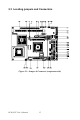
2.12 Front Panel Connector (CN22)
Next, you may want to install external switches to monitor and control the
PCM-9587. These features are optional: install them only if you need
them. The Front Panel connector (CN22) is a 14-pin male, dual in-line
header. It provides connections for a hard disk access indicator, LAN
Act., LAN Link, hardware reset, ATX power ON/OFF switch connector,
and power on indicator.
2.12.1 Power & HDD LED (pin 1-4 of CN22)
The HDD LED indicator for hard disk access is an active low signal (24
mA sink rate). Power supply activity LED indicator.
2.12.2 Reset switch (pin 13-14 of CN22)
If you install a reset switch, it should be an open single pole switch.
Momentarily pressing the switch will activate a reset. The switch should
be rated for 10 mA, 5 V.
2.13 Power connectors (CN25,CN5)
2.13.1 ATX power connector, +5V (CN5)
Supplies main power to the PCM-9587 (+5V) and to devices that require
it.
2.13.2 CPU Fan power supply connector (CN25)
Provides power supply +12V to CPU cooling fan, and fan speed detects
signal input.
2.14 ATX power ON/OFF switch con. pin 11-12 of CN22
2.14.1 ATX feature (CN5) & soft power switch (CN22)
The PCM-9587 can support an advanced soft power switch function, if an
ATX power supply is used. To enable the soft power switch function con-
nect the power on/off button to CN22. (A momentary type of button
should be used.)
Important
Make sure that the ATX power supply can take
at least a 10 mA load on the 5 V standby lead
(5VSB). If not, you may have difficulty power-
ing on your system.