IEEE 802.
Copyright The documentation and the software included with this product are copyrighted 2011 by Advantech Co., Ltd. All rights are reserved. Advantech Co., Ltd. reserves the right to make improvements in the products described in this manual at any time without notice. No part of this manual may be reproduced, copied, translated or transmitted in any form or by any means without the prior written permission of Advantech Co., Ltd. Information provided in this manual is intended to be accurate and reliable.
Product Warranty (2 years) Advantech warrants to you, the original purchaser, that each of its products will be free from defects in materials and workmanship for two years from the date of purchase. This warranty does not apply to any products which have been repaired or altered by persons other than repair personnel authorized by Advantech, or which have been subject to misuse, abuse, accident or improper installation.
Federal Communication Commission Interference Statement This equipment has been tested and found to comply with the limits for a Class B digital device, pursuant to Part 15 of the FCC Rules. These limits are designed to provide reasonable protection against harmful interference in a residential installation. This equipment generates uses and can radiate radio frequency energy and, if not installed and used in accordance with the instructions, may cause harmful interference to radio communications.
Technical Support and Assistance Step 1. Visit the Advantech web site at www.advantech.com/support where you can find the latest information about the product. Step 2. Contact your distributor, sales representative, or Advantech’s customer service center for technical support if you need additional assistance.
Safety Precaution - Static Electricity Follow these simple precautions to protect yourself from harm and the products from damage. 1. To avoid electrical shock, always disconnect the power from your PC chassis before you work on it. Don't touch any components on the CPU card or other cards while the PC is on. 2. Disconnect power before making any configuration changes. The sudden rush of power as you connect a jumper or install a card may damage sensitive electronic components.
Contents Chapter 1 Introduction......................................................................................................................... 1 Introduction ......................................................................................................................................... 1 Appearance ........................................................................................................................................ 1 Key Features .........................................
VLAN Tab.......................................................................................................................................... 30 Chapter 4 Advanced Settings ........................................................................................................... 31 Advanced Wireless Settings ............................................................................................................. 31 Wireless Security Settings ........................................................
View Network Flow Statistics ............................................................................................................ 53 View ARP Table ................................................................................................................................ 53 View Bridge Table ............................................................................................................................. 54 View Active DHCP Client Table ...............................................
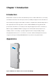
Chapter 1 Introduction Introduction EKI-6331AN is a feature rich wireless AP/ CPE which provides a reliable 5GHz wireless connectivity for industrial environments. The PoE injector enhances flexibility in deployment of this AP/ CPE even where the DC power supply is hard to fulfill. As an 802.11n compliant device, EKI-6331AN provides 3 times higher data rates than legacy 802.11a devices.
Key Features Compliant with IEEE802.11a/n IP55 waterproof certification MIMO 2 x 2 11n Embedded 16dBi dual-polarity directional antenna with external R-SMA connector for optional antenna Passive PoE WEP/WPA/WPA2/ IEEE 802.1 x authentication support IGMP snooping protocol support Specification Standard Support Wireless IEEE802.11a/n Ethernet IEEE802.3u MDI / MDIX 10/100 Fast Ethernet LAN IEEE802.11a/n wireless LAN interface Passive PoE, max.
Bridge ( WDS) AP repeater Antenna Default embedded 2T2R 16dBi dual-polarity directional antenna Reverse SMA Connector x 2 for external antennas *Switchable by software Modulation Techniques 802.11a OFDM 802.11n OFDM (BPSK, QPSK, 16-QAM, 64-QAM) Support Frequency FCC : 5725-5850 CE: 5470-5725 MHz (DFS band) Wireless Tx power and Rx Sensitivity Transmitted Power o 802.11a: 24dBm @ 6Mbps, 21dBm @ 54Mbps o 802.11an HT20: 23dBm @ MCS0/8, 20dBm@ MCS7/15 o 802.
Figure 2 Typical Application EKI-6331AN_User Manual Page 4
Chapter 2 Hardware Installation This chapter describes safety precautions and product information you have to know and check before installing EKI-6331AN. Preparation before Installation Professional Installation Required Please have EKI-6331AN installed by professional installer who is well trained in the RF installation and knowledgeable in the local regulations. Safety Precautions 1. To keep you safe and install the hardware properly, please read and follow these safety precautions. 2. 3.
Installation Precautions To have EKI-6331AN functioning well in outdoor environment, please read and follow these installation precautions while you are installing. 1. Users MUST use a proper and well-installed grounding and surge arrestor with EKI-6331AN; otherwise, lightening could easily cause fatal damage to the unit. EMD (Lightning) DAMAGE IS NOT COVERED UNDER WARRNTY. 2. Users MUST use the “Power cord & POE Injector” shipped in the box with EKI-6331AN.
Pole Mounting Ring Power Cord & POE Injector Start up manual & User’s manual CD Warning: Users MUST use the “Power cord & POE Injector” shipped in the box with EKI-6331AN. Use of other options will likely cause damage to the unit.
Hardware Installation Connect up 1. The bottom of EKI-6331AN is a movable cover. Loosen the screw with a screwdriver. Grab the cover and pull it back harder to take it out as the figure shown below. Figure 3 Move the Cover 2. Plug a standard Ethernet cable into the RJ45 port labeled “LAN 1”. Do not plug the cable into the RJ45 port labeled “LAN 2”.
The secondary Ethernet port (labeled LAN 2) is for EKI-6311GN or IP camera integration. To use it you need to enable the secondary port in advance before connecting with the EKI-6311GN or IP camera from EKI-6331AN Web Management as shown below. 3. Take out the power cord and POE injector from the gift box, and plug the power cord into the DC port of the POE injector as the below picture shows. Figure 5 Connect to POE Injector 4. Put what in the Step.2 and Step.
Figure 6 Plug the Ethernet cable to the RJ-45 jack of the injector 5. Press the black PWR button beside the LAN 1 Ethernet port. 6. Attach and fasten the removable cover to the bottom of the unit with the screw.
7. Power on EKI-6331AN by plugging the power adapter to the power socket. Using the External Antenna EKI-6331AN provides two reverse SMA antenna connectors if you prefer to use the external antenna for your application instead of the built-in directional antenna, please follow the steps below. 1. Remove the two plugs as circled below: 2. Connect your external antenna to the SMA-type connectors at the bottom of the EKI-6331AN.
Follow the steps described in Connect Up to finish the installation. Pole Mounting 1. Turn EKI-6331AN over. Put the pole mounting rings through the middle hole of it. Note that you should unlock the pole mounting ring with a screw driver before putting it through EKI-6331AN as the following right picture shows. Figure 7 Pole Mounting – Step 1 2. Mount EKI-6331AN steadily to the pole by locking the pole mounting ring tightly. The mounting ring supports pole diameter 32mm to 70mm.
Chapter 3 Basic Settings Factory Default Settings The following table shows EKI-6331AN factory default settings. You can re-acquire these parameters by default. If necessary, please refer to the “Restore Factory Default Settings”. Table 1 Factory Default Settings Features Factory Default Settings Username admin Password password Wireless Device Name apXXXXXX (X represents the last 6 digits of Ethernet MAC address) Operating Mode AP Data Rate Auto LAN IP Address 192.168.1.1 Subnet Mask 255.
Encryption None Wireless Separation Disable Access Control Disable SNMP Enable/Disable Enable Read Community Name Public Write Community Name Private IP Address 0.0.0.0 System Requirements Before configuration, please make sure your system meets the following requirements: A computer coupled with 10/ 100 Base-TX adapter; Configure the computer with a static IP address of 192.168.1.x, as the default IP address of EKI-6331AN is 192.168.1.1.
Enter the username (Default: admin) and password (Default: password) respectively and click “Login” to login the main page of EKI-6331AN. As you can see, this management interface provides 5 main options in the black bar above, which are Status, System, Wireless, Management and Tools.
Basic System Settings For users who use EKI-6331AN for the first time, it is recommended that you begin configuration from “Basic Settings” in “System” shown below: Figure 11 Basic System Settings Basic Settings Device Name: Specify the device name, which is composed of no more than 15 characters with (0-9), (A-Z), (a-z) or (-). Network Mode: Specify the network mode, including Bridge and Router.
fails. STP Forward Delay: STP Forward Delay is the time spent in detecting and learning network tree topology state before entering the forward state. Default time value is 1 sec. GPS Coordinate Settings: The GPS Coordinate Setting helps you mark the latitude and longitude of EKI-6331AN. Just enter the coordinates and click the Apply button. TCP/IP Settings Open “TCP/IP Settings” in “System” as below to configure the parameters for LAN which connects to the LAN port of EKI-6331AN.
will fall back to default static IP address. Use Fixed IP Address: Check this option. You have to specify a static IP address, subnet mask, default gateway and DNS server for EKI-6331AN manually. Make sure the specified IP address is unique on your network in order to prevent IP conflict. If EKI-6331AN is configured as Router mode, you need to configure some additional TCP/IP parameters for accessing the Internet.
before it is set to Router mode. To access the unit in Router mode via wired port, please type the WAN IP address to enter the web page for WAN is on wired port and LAN is on wireless port. Or, you can access device through the wireless device connected with the EKI-6331AN. In wireless client mode, users can access EKI-6331AN via its wired port, for WAN is on wireless port and LAN is on wired port when device is set to Router mode.
Select the time zone from the dropdown list. NTP Server Select the time server from the “NTP Server” dropdown list or manually input the IP address of available time server into “Manual IP”. (For example, 192.43.244.18 for NIST server. ) Hit “Apply” to save settings.
Global-Key Update: Check this option and specify the time interval between two global-key updates. Firewall Settings The firewall is a system or group of systems that enforce an access control policy between two networks. It may also be defined as a mechanism used to protect a trusted network from an un-trusted network. EKI-6331AN has capabilities of Source IP Filtering, Destination IP Filtering, Source Port Filtering, Destination Port Filtering, Port Forwarding as well as DMZ.
Figure 17 Destination IP Filtering Source Port Filtering: The source port filtering enable you to restrict certain ports of data packets from your local network to Internet through EKI-6331AN. Use of such filters can be helpful in securing or restricting your local network.
Destination Port Filtering: The destination port filtering enables you to restrict certain ports of data packets from your local network to Internet through EKI-6331AN. Use of such filters can be helpful in securing or restricting your local network. Figure 19 Destination Port Filtering Port Forwarding: The port forwarding allows you to automatically redirect common network services to a specific machine behind the NAT firewall.
DMZ: A Demilitarized Zone is used to provide Internet services without sacrificing unauthorized access to its local private network. Typically, the DMZ host contains devices accessible to the Internet traffic, such as Web (HTTP) servers, FTP servers, SMTP (e-mail) servers and DNS servers. Figure 21 DMZ Settings Basic Wireless Settings Open “Basic Settings” in “Wireless” as below to make basic wireless configuration.
Disable Wireless LAN Interface Check this option to disable WLAN interface, then the wireless module of EKI-6331AN will stop working and no wireless device can connect to it. Wireless Mode Four operating modes are available on EKI-6331AN. AP: EKI-6331AN establishes a wireless coverage and receives connectivity from other wireless devices. Wireless Client: EKI-6331AN is able to connect to the AP and thus join the wireless network around it.
bonding that allows EKI-6331AN to use two channels at once. Two options are available: Upper Channel and Lower Channel. Channel Mode 4 levels are available: 40MHz, 20MHz, 10MHz and 5MHz. 40MHz can enhance data throughput, but it takes more bandwidth, thus it might cause potential interference.
Extension Channel Protection Mode This is to avoid conflict with other wireless network and boost the ability of your device to catch all legacy devices transmissions. However, it may decrease wireless network performance. Compared to CTS-Self; the transmission amount of CTS-RTS is much lower. Enable MAC Clone Available in wireless client mode, it hides the MAC address of EKI-6331AN while displays the one of associated wireless client or the MAC address designated manually.
different profile settings such as security and VLAN ID to each SSID. To create a virtual AP, you may check the Enable box of the profile and click on the profile (eg. Profile 2) to configure wireless and security settings. Hit Apply to active the profile.
environment that may have potential risk. By disabling broadcast SSID, the STA cannot scan and find EKI-6331AN, so that malicious attack by some illegal STA could be avoided. Wireless Separation: Wireless separation is an ideal way to enhance the security of network transmission. Under the mode except wireless client mode, enable “Wireless Separation” can prevent the communication among associated wireless clients. WMM Support: WMM (Wi-Fi Multimedia) is a subset of 802.11e.
VLAN Tab If your network uses VLANs, you can assign one SSID to a VLAN, and client devices using the SSID are grouped in that VLAN. To allow users on the VLAN to access the WEB page of EKI-6331AN, you need to enable “Enable 802.1Q VLAN” and assign a management VLAN ID for your device. Make sure the assigned management VLAN ID is identical to your network VLAN ID to avoid failures of accessing the Web page of EKI-6331AN.
Chapter 4 Advanced Settings Advanced Wireless Settings Open “Advanced Settings” in “Wireless” to make advanced wireless settings. Figure 27 Advanced Wireless Settings A-MPDU/A-MSDU Aggregation The data rate of your EKI-6331AN except wireless client mode could be enhanced greatly with this option enabled; however, if your wireless clients don’t support A-MPDU/A-MSDU aggregation, it is not recommended to enable it. Short GI Under 802.
Fragmentation Length Specify the maximum size in byte for a packet before data is fragmented into multiple packets. Setting it too low may result in poor network performance. Leave it at its default of 2346 is recommended. Beacon Interval Specify the frequency interval to broadcast packets. Enter a value between 20 and 1024. DTIM Interval DTIM, which stands for Delivery Traffic Indication Message, is contained in the data packets. It is for enhancing the wireless transmission efficiency.
Layer2 protocols. Space in Meter To decrease the chances of data retransmission at long distance, EKI-6331AN can automatically adjust proper ACK timeout value by specifying distance of the two nodes. Flow Control It allows the administrator to specify the incoming and outgoing traffic limit by checking “Enable Traffic Shaping”. This is only available in Router mode.
Figure 28 Security Settings Network Authentication Open System: It allows any device to join the network without performing any security check. Shared Key: Data encryption and key are required for wireless authentication. (not available in Bridge/AP Repeater mode) Legacy 802.1x: Available in AP/Wireless Client mode, it provides the rights to access the wireless network and wired Ethernet.
WPA2 with RADIUS: Available in AP/Wireless Client mode, as a new version of WPA, only all the clients support WPA2, can it be available. If it is selected, AES encryption and RADIUS server is required. WPA&WPA2 with RADIUS: Available in AP mode, it provides options of WPA (TKIP) or WPA2 (AES) for the client. If it is selected, the data encryption type must be TKIP + AES and the RADIUS server must be set. WPA-PSK: It is a simplified WPA mode with no need for specific authentication server.
Access Control The Access Control appoints the authority to wireless client on accessing EKI-6331AN, thus a further security mechanism is provided. This function is available only under AP mode. Open “Access Control” in “Wireless” as below. Figure 29 Access Control Access Control Mode If you select “Allow Listed”, only those clients whose wireless MAC addresses are in the access control list will be able to connect to your AP.
WDS Settings Extend the range of your network without having to use cables to link the bridges by using the Wireless Distribution System (WDS): Simply put, you can link the bridges wirelessly. Open “WDS Settings” in “Wireless” as below: Figure 30 WDS Settings Enter the MAC address of another EKI-6331AN you wirelessly want to connect to into the appropriate field and click “Apply” to save settings. Note: WDS Settings is available only under Bridge and AP Repeater Mode.
Chapter 5 Management Remote Management EKI-6331AN provides a variety of remotes managements including Telnet, SNMP, FTP, SSH, HTTPS and exclusive WISE tool, making configuration more convenient and secure. With Normal selected, Telnet, SNMP and FTP are activated as default remote management options. To use secure management tools such as SSH, HTTPS and WISE, please select “Secure”. You may also choose “Customized” to enable any methods as desired.
Figure 32 SNMP Configuration Protocol Version Select the SNMP version, and keep it identical on EKI-6331AN and the SNMP manager. EKI-63331AN supports SNMP v2/v3. Server Port Change the server port for a service if needed; however you have to use the same port to use that service for remote management. Get Community Specify the password for the incoming Get and GetNext requests from the management station. By default, it is set to public and allows all requests.
Configure SNMPv3 User Profile For SNMP protocol version 3, you can click “Configure SNMPv3 User Profile” in blue to set the details of SNMPv3 user. Check “Enable SNMPv3 Admin/User” in advance and make further configuration. Figure 33 Configure SNMPv3 User Profile User Name Specify a user name for the SNMPv3 administrator or user. Only the SNMP commands carrying this user name are allowed to access EKI-6331AN. Password Specify a password for the SNMPv3 administrator or user.
None: No encryption is applied. DES: Data Encryption Standard, it applies a 58-bit key to each 64-bit block of data. Coovachilli Settings Coovachilli is a captive portal management which allows WLAN users to easily and securely access the Internet. Under Router mode, when Coovachilli is enabled, the IEEE 802.11b/g/n Wireless Access Point will force an HTTP client on a network to see a special web page (usually for authentication purposes) before using the Internet normally.
Enter the port number for billing Radius Shared Secret: Enter the secret key of the radius server Radius NAS ID: Enter the name of the radius server if any Radius Administrative-User Radius Admin Username: Enter the username of the Radius Administrator Radius Admin Password: Enter the password of the Radius Administrator Captive Portal UAM Portal URL: Enter the address of the UAM portal server UAM Secret: Enter the secret password between the redirect URL and the Hotspot.
Figure 35 Upgrade Firmware Click “Browse” to select the firmware file you would like to load; Click “Upload” to start the upload process; Wait a moment, the system will reboot after successful upgrade. Note: Do NOT cut the power off during upgrade, otherwise the system may crash! Backup/ Retrieve Settings It is strongly recommended you back up configuration information in case of something unexpected. If tragedy hits your device, you may have an access to restore the important files by the backup.
Restore Factory Default Settings EKI-6331AN provides two ways to restore the factory default settings: Restore factory default settings via Web From “Configuration File”, clicking “Reset Settings to Default” will eliminate all current settings and reboot your device, then default settings are applied.
Figure 38 Reboot Password From “Password Settings” in “Management”, you can change the password to manage your EKI-6331AN. Enter the new password respectively in “New Password” and “Confirm Password” fields; click “Apply” to save settings.
Note: The password is case-sensitive and its length cannot exceed 19 characters! Certificate Settings Under Client mode, when EAP-TLS is used, the RADIUS server must know which user certificates to trust. The Server can trust all certificates issued by a given CA. To import a user certificate, from Import User Certificates, click “Browse” and specify the location where the user certificate is placed. Click “Import”.
Monitoring Tools System Log System log is used for recording events occurred on EKI-6331AN, including station connection, disconnection, system reboot and etc. Open “System Log” in “Tools” as below. Figure 41 System Log Remote Syslog Server Enable Remote Syslog: Enable System log to alert remote server. IP Address: Specify the IP address of the remote server. Port: Specify the port number of the remote server.
Figure 42 Site Survey Tool Ping Watch Dog If the link is somehow broken and cut off your ability the log in to the unit, the ping watchdog has a chance to reboot due to loss of connectivity. Figure 43 Ping Watchdog Ping Watchdog Enable Ping Watchdog: To activate ping watchdog, check this checkbox. IP Address to Ping: Specify the IP address of the remote unit to ping.
Ping Interval: Specify the interval time to ping the remote unit. Startup Delay: Specify the startup delay time to prevent reboot before EKI-6331AN is fully initialized. Failure Count To Reboot: If the ping timeout packets reached the value, EKI-6331AN will reboot automatically. Date Rate Test The Data Rate Test allows you test the current RSSI at each data rate between EKI-6331AN.
try to adjust the antenna and see if the quality improves or not. Figure 45 Antenna Alignment Speed Test The speed test is to monitor the current data transmission (TX) and data reception (RX) rate with the remote EKI-6331AN. Enter the IP address of the remote EKI-6331AN, type in the user name/password and click “Test”. The result will display in the bottom STATUS. You may test single TX/RX or bi-direction.
Chapter 6 Status View Basic Information Open “Information” in “Status” to check the basic information of EKI-6331AN, which is read only. Information includes system information, LAN settings, wireless setting and interface status. Click “Refresh” at the bottom to have the real-time information. Figure 47 Basic Information View Association List Open “Connections” in “Status” to check the information of associated wireless devices such as MAC address, signal strength, connection time, IP address, etc.
Figure 48 Connection By clicking on the MAC address of the selected device on the web you may see more details including device name, connection time, signal strength, noise floor, ACK timeout, link quality, IP information, current data rate, current TX/RX packets.
View Network Flow Statistics Open “Flow Statistics” in “Status” to check the data packets received on and transmitted from the wireless and Ethernet ports. Click “Refresh” to view current statistics. Figure 49 Network Flow Statistics Poll Interval Specify the refresh time interval in the box beside “Poll Interval” and click “Set Interval” to save settings. “Stop” helps to stop the auto refresh of network flow statistics. View ARP Table Open “ARP Table” in “Status” as below.
Figure 50 ARP Table View Bridge Table Open “Bridge Table” in “Status” as below. Click “Refresh” to view current connected status.
expired for each DHCP leased client. Click “Refresh” to view current table. Figure 52 DHCP Client Table View Network Activities The network activities allows you to monitor the current Wireless and Ethernet TX/RX data traffic in graphical and numerical form on the Web of the Skyport. The chart scale and throughput dimension (bps, Kbps, Mbps) changes dynamically according to the mean throughput value. Throughput statistics can be updated manually using the “Refresh” button.
Chapter 7 Troubleshooting This chapter provides troubleshooting procedures for basic problems with EKI-6331AN. For warranty assistance, contact your service provider or distributor for the process. Q 1. How to know the MAC address of EKI-6331AN? MAC Address distinguishes itself by the unique identity among network devices. There are two ways available to know it. • Each device has a label posted with the MAC address. Please refer below.
Q 5. In wireless client mode, what if the wireless connection is not stable after associating with an AP? • Since EKI-6331AN comes with a built-in directional antenna, it is recommended make it face to the direction where the AP is to get the best connection quality. • In addition, you can start “Site Survey” in “Wireless Basic Settings” to check the signal strength. If it is weak or unstable (The smaller the number is, the weaker the signal strength is.
Appendix A. ASCII WEP can be configured with a 64-bit, 128-bit or 152-bit Shared Key (hexadecimal number or ACSII). As defined, hexadecimal number is represented by 0-9, A-F or a-f; ACSII is represented by 0-9, A-F, a-f or punctuation. Each one consists of two-digit hexadecimal.
Appendix B.
√ -staticnetm √ ask √ -staticgate √ way --static subnet mask --static gateway ip address √ √ -staticdns1 --static dns1 √ √ -staticdns2 --static dns2 √ √ -dhcpclient hostname -pppoecon √ nectstatus √ √ --obtains IP from pppoe ip server cipaddr √ -pppoeuser √ name √ -pppoepass √ word √ -pppoeserv √ ername √ -pppoecon √ nectmode √ -pppoeidleti √ --pppoe connect status -pppoelocal -pppoestati √ --dhcp client hostname me --pppoe static ip address --pppoe username --ppp
√ √ √ √ √ √ -wirelessmode --wireless mode -HTprotect --HT protect -wireless frequency/channel √ √ -frequency/channel (depends on country and wireless mode) √ √ -power --power √ √ -rate --rate √ √ -antenna --antenna type √ √ -antennaGain --antenna gain setings √ √ -wmm --wmm settings --wireless isolate √ √ -Isolation communication between clients √ √ √ √ √ --max sta connection -maxStaNum √ number --Whether manually limit the -StaNumLmt √ number o f station --wire
√ √ √ -1 --wireless wep key 1 √ √ √ -2 --wireless wep key 2 √ √ √ -3 --wireless wep key 3 √ √ √ -4 --wireless wep key 4 √ √ √ √ √ √ √ √ -wpa --wireless WPA setting -psk √ -reauthtime √ -keyupdate √ √ √ √ √ √ √ √ √ -eap --wireless pre-shared key (PSK) for WPA-PSK --wireless WPA re-auth period (in seconds) --enable wireless WPA global key update --WPA EAP setting -eaptype -innereapty pe --WPA EAP Type --WPA inner EAP Type √ √ -username --WPA user name √ √ -l
√ √ -Isolation --wireless separation √ √ -wmm --WMM Support √ √ -MaxStaNum --Max Station Number √ √ -StaNumLmt √ √ number o f station --wireless authentication -authentication √ √ -encryption √ √ -default √ --Whether manually limit the √ type --wireless data encryption --wireless wep default key index -wpa √ --wireless WPA setting --list of associated wireless -association clients √ √ √ √ -active --enable 802.
settings √ √ √ -enable √ -addrule √ -delerule √ -rulelist --destination port filter enable --add a destination port filter rule --delete destination port filter rule --show destination port filter rule lists √ √ √ √ -enable --port forward enable √ √ -addrule --add a port forward rule √ -delerule --delete port forward rule -portforward √ --port forward settings -rulelist --show port forward rule lists √ √ -dmzenable --dmz enable √ √ -dmzipaddr --dmz ip address √ √ --remo
√ √ √ -name --name √ -password --password -accessTyp √ e √ -authentica √ tion √ √ √ √ √ √ √ √ -Privacy coovachilli -coovaChilliEnable -primaryRadiusServ √ √ --Authentication Protocol --privacy protocol --CoovaChilli setting er √ --access type --Coovachilli Enable --Primary RADIUS Server -secondaryRadiusSe --Secondary RADIUS rver Server --RADIUS Authentication √ -radiusAuthPort Port √ √ -radiusAcctPort --RADIUS Accounting Port √ √ -radiusSharedSecret --RADIUS Shared S
√ statistics --statistics √ -Wireless --Wireless LAN √ -Ethernet --Ethernet LAN √ √ log list --syslog list √ password --system password √ reset --restore factory √ reboot --reboot system √ exit --logout from CLI EKI-6331AN_User Manual Page 66
Appendix C. GPL Declamation PUBLIC SOFTWARE DECLAMATION In the software we delivered, there may contains some public software, if it is, please read below carefully: 1. Definition “Public Software”, when applicable, shall mean that portion of the Licensed Software, in source code form, set forth in the below Table, and provided under the terms set forth in the Section 5, the indicated website, the complete license terms can be found.
to any such Public Software, as set forth in its presentation on website. 3. Limited Liability The supplier hereby express that the supplier shall have no liability for any costs, loss or damages resulting from Licensee’s breach of the terms and conditions applicable to use, conversion or combination of the licensed software with or into Public Software. 4. NO WARRANTY This program or licensed software is distributed in the hope that it will be useful, but WITHOUT ANY WARRANTY.
Software Inc., /Webserver/2.1. 1992-2000. 8/webs218.tar.g z hostapd Copyright (c) http://hostap.epit GNU GENERAL http://www.gnu.or 2002-2006, Jouni est.fi/releases/h PUBLIC LICENSE g/licenses/old-lice Malinen ostapd-0.4.8.tar. Version 2 nses/gpl-2.0.html and contributors wpa_supplic Copyright (c) http://hostap.epit GNU GENERAL http://www.gnu.or ant 2003-2005, Jouni est.fi/releases/w PUBLIC LICENSE g/licenses/old-lice Malinen pa_supplicant-0.
ns/vsftpd-1.1.2.t Version 2 nses/gpl-2.0.html ftp://ftp.kernel.or GNU GENERAL http://www.gnu.or g/pub/linux/kern PUBLIC LICENSE g/licenses/old-lice el/v2.6/linux-2.6. Version 2 nses/gpl-2.0.html ar.gz linux 15.tar.bz2 iptables Copyright ftp://ftp.netfilter.o GNU GENERAL http://www.gnu.or 2000-2004 rg/pub/iptables/i PUBLIC LICENSE g/licenses/old-lice netfilter project ptables-1.3.6.tar. Version 2 nses/gpl-2.0.html http://www.netfilter bz2 .org/ openssl Copyright (c) http://www.
shemminger@osd ute2 Version 2 nses/gpl-2.0.html l.org Alexey Kuznetsov kuznet@ms2.inr.a c.ru Pppd Paul Mackerras ftp://ftp.samba.or
Appendix D. Country Channel List EKI-6331AN supports country selection. Channels may vary upon each country’s regulation. The following tables list the channel with country code in each bandwidth.
Finland France Germany Greece Hungary Iceland Ireland Italy Latvia Liechtenstein Lithuania Luxembourg Macedonia Malta Netherlands Norway Poland Portugal Romania Slovakia Slovenia Spain Sweden United Kingdom Table 6 Other Countries Country Mode Channel list 40MHz 20MHz 10MHz 5MHz 149/150/151/152/ 149/151/153/155/ India 11a 149/153/157/ 149/153/157/161/ 157/159/161/163/1 5725-5875MHz 161 165/169/173 65/167/169/171/17 3 153/154/155/156/ 157/158/159/160/ 161/162/163/164/ 165/166/167/168/ 169/170/17
Korea Russia 11a 5470-5650MHz 5725-5825MHz 100/104/108/ 100/101/102/103/ 112/149/153/ 104/105/106107/ 157/161 *Russia: Does not 100/104/108/112/ 116/149/153/157/ 161 100/102/104/106/ 108/109/110/111/ 108/110/112/114/ 112/113/114/115/ 116/149/151/153/1 116/149/150/151/ 55/157/159/161/ 152/153/154/155/ support 156/157/158/159/ HT40.