User Manual APAX-5000 Series I/O Modules
Copyright The documentation and the software included with this product are copyrighted 2008 by Advantech Co., Ltd. All rights are reserved. Advantech Co., Ltd. reserves the right to make improvements in the products described in this manual at any time without notice. No part of this manual may be reproduced, copied, translated or transmitted in any form or by any means without the prior written permission of Advantech Co., Ltd. Information provided in this manual is intended to be accurate and reliable.
Declaration of Conformity CE This product has passed the CE test for environmental specifications when shielded cables are used for external wiring. We recommend the use of shielded cables. This kind of cable is available from Advantech. Please contact your local supplier for ordering information. FCC Class A Note: This equipment has been tested and found to comply with the limits for a Class A digital device, pursuant to part 15 of the FCC Rules.
Safety Instructions 1. 2. 3. Read these safety instructions carefully. Keep this User Manual for later reference. Disconnect this equipment from any AC outlet before cleaning. Use a damp cloth. Do not use liquid or spray detergents for cleaning. 4. For plug-in equipment, the power outlet socket must be located near the equipment and must be easily accessible. 5. Keep this equipment away from humidity. 6. Put this equipment on a reliable surface during installation.
Chapter 1 Overview...............................................1 1.1 Introduction ............................................................................................... 2 Table 1.1: Supported I/O Module List.......................................... 2 I/O Wiring .................................................................................................. 3 Removing the I/O Terminal ....................................................................... 4 Labeling the Terminal............
Chapter 4.1 4.2 APAX-5002 2-slot Backplane Module..................................................... 54 APAX-5001 1-slot Backplane Module..................................................... 55 5 Error Handling and Diagnostics ...... 57 5.1 Error Handling and Diagnostics ..............................................................
Chapter 1 Overview 1
1.1 Introduction This manual will discuss the specifications, functions and application wiring of the APAX-5000 series of I/O modules. Advantech provides different APAX-5000 I/O modules for various applications. The following table outlines Advantech's supported I/O modules. Table 1.
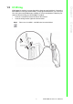
APAX-5000 I/O modules leverage detachable clamp type terminal blocks. Comparing with traditional screw type terminal blocks, clamp type terminal blocks can save up to 75% wiring time and provide better reliability for shock and vibration. Follow the procedures below for wiring your APAX-5000 I/O module. 1. Insert the screw driver into the left hole of the terminal. 2. Insert the wiring into the right hole of the terminal. Please use # 14 AWG ~ 28 AWG wire for terminal block.
1.3 Removing the I/O Terminal APAX-5000 I/O modules provide detachable terminal blocks that are convenient when wiring needs to be changed, because the terminal block can removed and the module doesn't need to be. Refer to the figures below to remove the terminal block. Warning! APAX-5000 I/O modules can be categorized into four categories: AI, AO, DI and DO.
Advantech provides write-on labels for each APAX-5000 I/O module. This write-on label has two sides, one with the model name, specifications and a wiring diagram, while the other side allows users to write information in by themselves. Refer to the figures below for the write-on label details. Chapter 1 1.
1.5 Jumper Settings Some I/O modules need to be configured manually through the onboard jumpers. This section will show you how to adjust the jumper settings. 1. 2. 3. Pull out the write-on label and you can see the location of the jumper. You can use the screw driver to adjust the jumper setting. Once the jumper setting is done, slide the write-on label back to its position.
The controller identifies each APAX-5000 I/O module through the ID number. Therefore, you need to set ID number for each I/O module by the rotary ID switch on the front side. Rotate that ID switch and point the hole on the central axis to corresponding ID number ("0" ~ "F"). Refer to figures below for the location of the rotary ID switch and how to set the ID number by the rotary ID switch. Chapter 1 1.
You can distinguish if the ID number is doubled by the front LED. When the LED color is green, only 0 ~ 15 ID number is used (0 ~ 15 according to the rotary ID switch). Once the LED color is orange, the ID number is doubled (16~31 according to the rotary ID switch). Refer to figure below for its location and how to configure it.
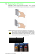
Mechanical Assembly and Power Connection 1.7.1 Wiring Power Input to the Backplane 1. Connect the power supply wire to the power connectors on the 2-slot APAX5002 backplane module. Warning! If you use APAX-5000 digital modules in the same system, use different power supplies for the system and the the digital channels on the modules to ensure isolation protection between digital channels and system. 2. Insert one APAX-5000 I/O module on that APAX-5002 backplane module.
3. Lock that APAX-5000 I/O module to the APAX-5002 backplane by pulling down the module locks. 4. Insert another APAX-5000 I/O module on the same APAX-5002 backplane. Use tongue-and-groove slots to move the module. 5. Lock that APAX-5000 I/O module to the APAX-5002 backplane by pulling down the module locks.
If you need more than one APAX-5000 I/O module, stack another APAX-5002 backplane to the original APAX-5002 backplane. Chapter 1 6. Overview Warning! When you assembly different backplanes together, remember to turn off the power connected to the backplane. If not, the backplanes may be damaged. Turn on the power again after you complete the assembly for all backplanes. 7. Lock the stacked APAX-5002 backplane to the original APAX-5002 backplane by the backplane locks.
8. Insert another APAX-5000 I/O module on the second APAX-5002 backplane. 9. Lock that APAX-5000 I/O module to the second APAX-5002 backplane by pull down the module locks, similar as step 5. 10. If needed, repeat step 8 ~ 9 to have another APAX-5000 I/O module on the same APAX-5002 backplane. If you need more APAX-5000 I/O module, repeat Step 6 ~ Step 10 until all necessary APAX-5000 I/O modules are inserted on the backplanes.
Chapter 1 Overview 1.7.2 Using the APAX-5343E Power Supply Module APAX-5000 I/O modules can also be powered by the APAX-5343E power supply module, connected to the left side of the whole system. The power can be transferred to APAX-5000 I/O modules though the backplanes. Note! 1. 2. Refer to APAX-5520 Hardware Manual for APAX-5343E specification. Follow the procedure described in Section 1.7.1 to assembly APAX-5000 I/O modules into one complete system.
APAX-5000 I/O Series User Manual 14
4. Lock the stacked APAX-5343E backplane with the APAX-5002 backplane by the backplane locks on the APAX-5002 backplane. 5. Insert the upper case of APAX-5343E back to its backplane. Use tongue-andgroove slots to move the upper case. Overview Stack the backplane of APAX-5343E to the left side of the first APAX-5002 backplane in the system. Chapter 1 3.
6. Lock the upper case of APAX-5343E to its backplane by pulling down the module locks on the upper case. Connect AC power code to the power connectors on the upper case of APAX-5343E. Then the whole system is powered-on. 1.8 Decommission and Disposal APAX-5000 I/O modules support hot-swap functionality. It means the I/O module can be removed from the backplane or inserted on the backplane when the complete system is power-on. This can significantly help to make it more convenient for system maintenance.
Detach APAX-5000 I/O module from the backplane. Chapter 1 2. Overview Repeat Step 1 ~ Step 2 for all the APAX-5000 I/O modules you want to remove. It is the similar when you insert APAX-5000 I/O modules back to the backplane. First, insert APAX-5000 I/O module to backplane. Then, pull down the two module locks to lock on the backplane, and APAX-5000 I/O module will be power-on and can be used. The device must be fully dismantled in order to dispose of it.
2. Attach the APAX-5002 backplane on the DIN rail. 3. Repeat Step 1 ~ Step 2 until necessary APAX-5002 backplanes are all attached on the DIN rail. Note! 4. 5. 6. 7. When the total number of APAX-5520 and APAX-5000 I/O modules is odd, you can use APAX-5001 (1-slot backplane) as the last backplane in the system. And the procedure to attach APAX-5001 on the DIN rail is similar as APAX-5002. Move all backplanes to stack them together.
Mount the APAX-5000 I/O module to a wall (panel) through backplane using two screws per module. Use M4 or #8 panhead screws. Refer to figure below for the dimensional template: Chapter 1 1.9.2 Wall (Panel) Mounting Overview Below are the procedures for the wall (panel) mounting: 1. Pull down the DIN-rail lock at the back of the first APAX-5002 backplane.
2. Hang the APAX-5002 backplane onto the screw on the wall (panel). The screw for APAX-5002 to hang should be special-designed. We have provided it in accessory. (Diameter: 9 mm, length: 16 mm, height of head: 2.7 mm) 3. Mount the first APAX-5002 backplane to the wall (panel) using two standard M4 or #8 panhead screws. We also provide the two screws in accessory. (Diameter: 7 mm, length: 8 mm, height of head: 2.
5. Mount the second APAX-5002 backplane to the wall (panel) using two standard M4 or #8 panhead screws. Overview Stack Another APAX-5002 backplane to original backplane. Lock the two backplanes together. Chapter 1 4.
6. Repeat Step 4 ~ Step 5 until all necessary APAX-5002 backplane are screwed on the wall (panel). Note! 7. 8. When the total number of APAX-5000 I/O modules is odd, you can use APAX-5001 (1-slot backplane) as the last backplane in the system. The procedure to attach APAX-5001 on the wall is similar as APAX-5002. Insert all necessary APAX-5000 I/O modules to the backplanes. (Similar to Step 2, Step 4 and Step 8 in section 1.7.
Chapter 1 Overview We suggest remaining enough clearance space from enclosure walls and adjacent equipments. Allow 50 mm (2 in.) of space on all sides, as shown below. This provide ventilation and makes assembly more easily.
APAX-5000 I/O Series User Manual 24
Chapter 2 2 Analog Input/Output Modules
2.1 Analog Input Modules Analog input modules use an A/D converter to convert sensor voltage, current, thermocouple or RTD signals into digital data. The analog input modules protect your equipment from ground loops and power surges by providing opto-isolation of the A/ D input and transformer based isolation up to 2,500 VDC. 2.1.1 APAX-5013 8-ch RTD Module The APAX-5013 is a 16-bit, 8-channel RTD input module that features programmable input ranges on all channels.
Chapter 2 Application Wiring APAX-5013 Technical Specifications Channels: 8 Input Impedance: >20 MΩ Input Type: Pt-100, Pt-200, Pt-500, Pt-1000, Balco, Ni 518 RTD (3-wire) Temperature Range: Pt-100,Pt-200,Pt-500,Pt-1000: -120~130° C, -200~850° C – Supports IEC 60751 ITS90 (0.03851Ω/Ω/° C) and JIS C 1604 (0.03916 Ω/Ω/° C) – Balco 500: -30 ~ 120° C – Ni 518: -80 ~ 100° C, 0 ~ 100° C Configure Different Range for Each Channel: Yes Resolution: 16-bit Accuracy: ±0.
2.1.2 APAX-5017 12-ch Analog Input Module The ADAM-5017 is a 16-bit, 12-channel analog differential input module that provides programmable input ranges on all channels, and different channels can be configured using different ranges. It accepts voltage and current inputs. Adjust the switch (refer to Section 1.5) to define each channel as voltage or current input. Refer to the figure below to see how to define the input type by the jumper.
Note! You can use the jumpers to configure each analog input channel type (voltage or current). Refer to Section 1.5 for the location of the jumpers. There are a total of 12 jumpers and each is specific for one channel. Refer to figure below for how to configure analog input channel type. In this example, channels 1, 2, 7, 8 and 9 are setting as current input channels, while other channels are setting as voltage input channels.
Technical Specifications of APAX-5017 Channels: 12 (Differential) Input Impedance: >10 MΩ (Voltage), 120Ω (Current) Input Type: V, mV, mA Voltage/Current Range: ±150mV,±500mV,±1V,±5V,±10V,±20mA,0~20mA,4~20 mA Configure Different Range for Each Channel: Yes Accuracy: ±0.1% or better (Voltage), ±0.
APAX-5017H is an 12-ch analog differential input module that provides programmable input ranges on each channel. Its sampling rate depends on the data format received: up to 1000 sample/second (per channel). The module provides 2500 VDC optical isolation between channels and backplane bus. If any high voltage or current damage the channels, the whole system (backplanes, other modules, and control unit) won't be affected because it is already isolated. Chapter 2 2.1.
Note! You can use the jumpers to configure each analog input channel type (voltage or current). Refer to Section 1.5 for the location of the jumpers. There are a total of 12 jumpers and each is specific for one channel. Refer to figure below for how to configure analog input channel type. In this example, channels 1, 2, 7, 8 and 9 are setting as current input channels, while other channels are setting as voltage input channels.
Channels: 12 Input Impedance: 2MΩ (Voltage), 120 Ω (Current) Input Type: V, mV, mA Input Range: 0 ~ 500 mV, ±10 V, 0 ~ 10 V, 0 ~ 20 mA, 4 ~ 20 mA Configure Different Range for Each Channel: Yes Accuracy: ±0.1% or better (voltage), ±0.
2.1.4 APAX-5018 12-ch Thermocouple Input Module The APAX-5018 is a 16-bit, 12-channel thermocouple input module that features programmable input ranges on all channels. It accepts millivolt inputs (±50 mV, ±100 mV, ±500 mV), voltage inputs (±1 V, ±2.5 V), current input (±20 mA, 0~20mA, 4~20mA) and thermocouple input (Type J, K, T, R, S, E, B). An external CJC on the plug-in terminal is designed for accurate temperature measurement.
You can use the jumpers to configure each analog input channel type (voltage/thermocouple or current). Refer to Section 1.5 for the location of the jumpers. There are a total of 12 jumpers and each is specific for one channel. Refer to figure below for how to configure analog input channel type. In this example, channels 1, 2, 7, 8 and 9 are set as current input channels, while other are set as voltage input channels.
APAX-5018 Specifications Channels: 12 (Differential) Input Type: V, mV, mA, Thermocouple Voltage/Current Range: ±50mV, ±100mV, ±500mV, ±1V, ±2.5V, ±20mA, 0~20mA, 4~20 mA Voltage and Current Accuracy: ±0.1% or better (Voltage), ±0.2% or better (Current) at 25° C Temperature Range and Accuracy: Type Range Accuracy Type J -210 ~ 1200° C Type K -270 ~ 1372° C Type T -270 ~ 400° C Type E -270 ~ 1000° C Type R 0 ~ 1768° C Type S 0 ~ 1768° C Type B 300 ~ 1820° C ±1.0° ±1.0° ±1.0° ±1.
Protection Isolation: 2,500 VDC (Between channels and backplane bus) Environment Operating Temperature: -10 ~ 60° C (when mounted vertically) Storage Temperature: -40 ~ 70° C Relative Humidity: 5 ~ 95% (non-condensing) General Dimensions (W x H x D): 30 x 139 x 100 mm Weight: 170 g Power Consumption: 3.
2.2 Analog Output Modules 2.2.1 APAX-5028 8-ch Analog Output Module The APAX-5028 is a 8-channel analog output module. It uses the D/A converter controlled by the system module to convert the digital data into output signals. You can specify slew rates and start up currents through the configuration software. For each channel, voltage and current can be used by connecting to different terminal. The module provides 2500 VDC optical isolation between channels and backplane bus.
Chapter 2 Application Wiring Note! The common terminals are physically connected together and to the backplane power supply ground. 39 APAX-5000 I/O User Manual Analog Input/Output Modules Figure 2.
2.2.2 APAX-5028 Specifications Channels: 8 Output Type: V, mA Output Range: ±2.5 V, ±5 V, ±10 V, 0~2.5 V, 0~5 V, 0~10 V, 0~20 mA, 4~20 mA Configure Different Range for Each Channel: Yes Resolution: 14-bit Accuracy: ±0.1% of FSR at 25° C Settling Time: About 50 μs to 0.01% Output Latency: 500 μs Slew Rate: 0.
Chapter 3 3 Digital Input/Output Modules
3.1 Digital Input/Output Modules 3.1.1 APAX-5040 24-ch Digital Input Module The APAX-5040 features 24 digital input (sink/source) channels. The APAX-5040 module's digital input channels can accept a 2-wiring input from a DC voltage source, to determine the state of limits, standard switches or proximity switches. The digital input channels offer LED to indicate digital status. The module provides 2500 VDC optical isolation between channels and backplane bus.
Protection Isolation: 2,500 VDC (Between channels and backplane bus) Over Voltage Protection: ±70 VDC Environment Operating Temperature: -10 ~ 60° C (when mounted vertically) Storage Temperature: -40 ~ 70° C Relative Humidity: 5 ~ 95% (non-condensing) General Dimensions (W x H x D): 30 x 139 x 100 mm Weight: 160 g Power Consumption: 2 W @ 24 VDC (typical) Status Display: LED per channel – On: Logic level “1” – Off: Logic level “0” 43 APAX-5000 I/O Series User Manual Digital Input/Output
3.1.2 APAX-5045 24-ch Digital Input/Output Module The APAX-5045 features 12 digital input (sink/source) and 12 digital output (sink) channels. The APAX-5045 module's digital input channels can accept a 2-wiring input from a DC voltage source, to determine the state of limits, standard switches or proximity switches. The APAX-5045 module's digital output channels can generate discrete signal to external devices and change its output value to control the devices.
Chapter 3 Application Wiring Warning! When you connect DO channel with inductive load, we suggest adding one diode in the circuit to protect the APAX-5045 module. (Refer to figure below) APAX-5045 Specifications Digital Input Channels: 12 Points per Common: 12 Type: Sink/Source (Wet Contact) Input Voltage Rated Value: 24 VDC – For "0" signal: -5 ~ 5 VDC – For "1" signal: 15 ~ 30 VDC and -15 ~ -30 VDC Input Impedance: 5.4 kΩ Input Current: typical 4.
Digital Output Channels: 12 Type: Sink Voltage Range: 8 ~ 35 VDC Rated Output Current at signal "1": 0.5 A (per channel) Permitted Output Current (at signal "1"): max. 0.75 A Output Current at signal "0" (leakage current): 0.1 mA Lamp Load: max. 5W On-State Voltage Drop: 0.15 V at 0.5 A Switch Rate: – For resistive load: max. 300 Hz – For inductive load: max. 20 Hz – For lamp load: max.
The APAX-5046 features 24 digital output (sink) channels. The digital output channels offer short-circuit protection and LED to indicate digital status. The module provides 2500 VDC optical isolation between channels and backplane bus. If any high voltage or current damage the channels, the whole system (backplanes, other modules, and control unit) won't be affected because it is already isolated. Figure 3.5 APAX-5046 Module Front View Application Wiring Figure 3.
APAX-5046 Specifications Digital Output Channels: 24 Type: Sink Voltage Range: 8 ~ 35 VDC Rated Output Current at signal "1": 0.5 A (per channel) Permitted Output Current (at signal "1"): max. 0.75 A Output Current at signal "0" (leakage current): 0.1 mA Lamp Load: max. 5W On-State Voltage Drop: 0.15 V at 0.5 A Switch Rate: – For resistive load: max. 300 Hz – For inductive load: max. 20 Hz – For lamp load: max.
3.2.1 APAX-5060 12-ch Relay Output Module Figure 3.7 APAX-5060 Module Frontal View 49 APAX-5000 I/O Series User Manual Digital Input/Output Modules The APAX-5060 relay output module provides 12 relay channels of Form A. Switches can be used to control the relays. The digital output channels offer short-circuit protection and LED to indicate digital status. The module provides 2500 VDC optical isolation between channels and backplane bus.
Application Wiring Figure 3.8 Wiring for APAX-5060 Warning! When you connect DO channel with inductive load, we suggest adding one diode in the circuit to protect the APAX-5060 module.
Protection Isolation: 2,500 VDC (Between channels and backplane bus) Environment Operating Temperature: -10 ~ 60° C (when mounted vertically) Storage Temperature: -40 ~ 70° C Relative Humidity: 5 ~ 95% (non-condensing) General Dimensions (W x H x D): 30 x 139 x 100 mm Weight: 195 g Power Consumption: 2 W @ 24 VDC (typical) Status Display: LED per channel – On: Logic level “1” – Off: Logic level “0” 51 APAX-5000 I/O Series User Manual Digital Input/Output Modules Relay Output Channels:
APAX-5000 I/O Series User Manual 52
Chapter 4 4 Backplane Modules
4.1 APAX-5002 2-slot Backplane Module APAX-5002 is an interface between CPU module, coupler and I/O modules. Different APAX-5002 can be stacked together. Power and data can be transferred to I/O modules inserted on the APAX-5002. You can use external power supply or APAX-5343E power supply module to give power to the backplanes and I/O modules. Refer to Section 1.7.1 and 1.7.2 for the operation procedure. If the APAX-5002 is powered-on, you can see the LED to indicate the module is working.
APAX-5001 functionality is the same as APAX-5002. And it is used to be connected at the right side of APAX-5002 when the total I/O module number is odd. Power and data can be transferred to I/O modules inserted on the APAX-5001. If the APAX-5001 is power-on, you can see the LED lit on to indicate the module is working well.
APAX-5000 I/O Series User Manual 56
Chapter 5 5 Error Handling and Diagnostics
5.1 Error Handling and Diagnostics There is one power LED on the front panel of any APAX-5000 I/O module. When the module is power-on, the LED will be lit. For analog I/O module, the LED color is green. For digital I/O module, the LED color is green or orange, depending on the module ID number. Refer to Section 1.6 for more details. Except for showing the module power status and ID number, this LED is also designed to diagnose module status.
LED continues flashing 4 times every 2 seconds Solution: ID number of that I/O module conflicts with ID number of another I/O module 1. Check ID number of all I/O modules in the same system. Adjust the ID number to avoid different I/O modules with the same ID number. Refer to Section 1.6 for how to adjust ID number. Then reboot the system and it should work fine. (The LED should stop flashing) 2.
APAX-5000 I/O Series User Manual 60