UNO-2052E GX2-400 UNO with 2xCAN, LAN, USB, RS-232 User Manual
Copyright The documentation and the software included with this product are copyrighted 2007 by Advantech Co., Ltd. All rights are reserved. Advantech Co., Ltd. reserves the right to make improvements in the products described in this manual at any time without notice. No part of this manual may be reproduced, copied, translated or transmitted in any form or by any means without the prior written permission of Advantech Co., Ltd. Information provided in this manual is intended to be accurate and reliable.
Product Warranty (2 years) Advantech warrants to you, the original purchaser, that each of its products will be free from defects in materials and workmanship for two years from the date of purchase. This warranty does not apply to any products which have been repaired or altered by persons other than repair personnel authorized by Advantech, or which have been subject to misuse, abuse, accident or improper installation.
CE This product has passed the CE test for environmental specifications. Test conditions for passing included the equipment being operated within an industrial enclosure. In order to protect the product from being damaged by ESD (Electrostatic Discharge) and EMI leakage, we strongly recommend the use of CE-compliant industrial enclosure products. FCC Class A This equipment has been tested and found to comply with the limits for a Class A digital device, pursuant to Part 15 of the FCC Rules.
Packing List Before setting up the system, check that the items listed below are included and in good condition. If any item does not accord with the table, please contact your dealer immediately. The UNO-2052E Series comes with the following items: • Plug-in 2P female screw terminal for power • Mini jumper 2.
UNO-2052E User Manual vi
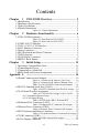
Contents Chapter 1 UNO-2052E Overview .................................... 2 1.1Introduction .................................................................................... 1.2Hardware Specifications................................................................. 1.3Safety Precautions .......................................................................... 1.4Chassis Dimensions........................................................................ 2 2 3 4 Figure 1.1: Chassis Dimensions ........
Table A.9:VGA Adaptor Cable Pin Assigns ............... 23 A.9CompactFlash Master/Slave Jumper Setting (JP3) .....................
CHAPTER 1 2 UNO-2052E Overview This chapter gives background information on the UNO-2052E. It shows you the UNO-2052E overview and specifications.
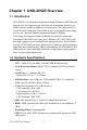
Chapter 1 UNO-2052E Overview 1.1 Introduction UNO-2052E is an embedded Application Ready Platform (ARP) that can shorten your development time and offer rich networking interfaces to fulfill extensive needs in different kind of projects. The Advantech Universal Network Controller (UNO-2000 series) is designed for providing services on a network enabled Application Ready Platform. Leveraging field-approved and worldwide-accepted OS technology, Advantech UNO-2000 series provides a Windows CE .
• Power Supply: 9~36 VDC • Anti-Shock: 20G@DIN IEC 68 section 2-27, half sine, 11ms 50G@Wall/Panel IEC 68 section 2-27, half sine, 11ms. • Anti-Vibration: 2G w/ CF@IEC 68 section 2-6, sine, 5~500Hz, 1 Oct./min, 1hr/axis. 1G w/ HDD@IEC 68 section 2-6, sine, 12~300Hz, 1 Oct./min, 1hr/ axis. • Operating Temperature: -10~55° C @ 5~85% related humidity. • Related Humidity: 95% @ 40° C. • Power Consumption: 0.6 A max under +24 V power input or 1.
1.4 Chassis Dimensions Figure 1.
CHAPTER 2 2 Hardware Functionality This chapter shows how to set up the UNO-2052E’s hardware functions, including connecting peripherals, switches and indicators.
Chapter 2 Hardware Functionality 2.1 UNO-2052E Peripherals The following two figures show the connectors on UNO-2052E. The following sections give you detail information about function of each peripheral. Figure 2.
Figure 2.
2.2 COM1: RS-232 Interface The UNO-2052E offers one standard RS-232 serial communication interface port (COM1). Please refer to A.2 for the pin assignments. 2.3 CAN 1~CAN 2: CAN Interface The UNO-2052E offers two CAN serial communication interface ports. COM3 and COM4. Please refer to Appendix A.3 for the pin assignments.
2.6 PS/2 Keyboard and Mouse Connector The UNO-2052E provides a PS/2 keyboard and PS/2 mouse connector. A 6-pin mini-DIN connector is located on the rear panel of the UNO-2052E. The UNO-2052E comes with an adapter to convert from the 6-pin miniDIN connector to two 6-pin mini-DIN connectors for PS/2 keyboard and PS/2 mouse connection. Please refer to Appendix A.5 for its pin assignments. 2.7 USB Connector The USB connector is used for connecting any device that conforms to the USB interface.
2.9 RESET: Reset Button Press the "Reset" button to activate a reset function.
CHAPTER 3 2 Initial Setup This chapter provides information on how to setup UNO-2052E.
Chapter 3 Initial Setup 3.1 Inserting a CompactFlash Card The procedure for installing a CompactFlash card into the UNO-2052E is as follows, please follows these steps carefully. Step 1: Remove the power cord. Step 2: Unscrew the four screws from the rear panel of the UNO-2052E. Step 3: Remove the rear panel. Step 4: Plug a CompactFlash card with the user’s OS and application program into a CompactFlash card slot on the board. Step 5: Screw back the rear panel with the four screws. 3.
3.4 BIOS Setup and System Assignments UNO-2052E uses the Advantech SOM-2354 CPU module. Further information about the SOM-2354 CPU module can be found in the SOM-2354 user manual. Please note that you can try to “LOAD BIOS DEFAULTS” from the BIOS Setup manual if the UNO-2052E does not work properly.
UNO-2052E User Manual 14
APPENDIX A 2 System Settings This chapter provides information on the system settings of UNO-2052E.
Appendix A A.1 Board Connectors and Jumpers There are connectors and jumpers on the UNO-2052E board. The following sections tell you how to configure the UNO-2052E hardware setting. Figure A-1 and figure A-2 show the locations of UNO2052E connectors and jumpers. Figure A.
Figure A.
Table A.
A.2 RS-232 Standard Serial Port (COM1) 1 2 3 4 5 6 7 8 9 Table A.
A.3 CAN Serial Port Pin Assignment Table A.3: CAN Port Pin Assigns (CAN1~CAN2) Pin CAN Signal Name 1 N/A 2 CAN-L 3 GND 4 N/A 5 N/A 6 N/A 7 CAN-H 8 N/A 9 N/A 1 CAN-L 2 GND 3 4 5 6 7 CAN-H 8 9 A.3.1 Termination Resistor Setup Terminal resistors are factory installed to allow for impedance matching. These resistors can be enabled by utilizing JP6 (shown below). The value of the resistor should equal the characteristic impedance of the signal wires (approximately 120 ohms).
A.3.2 CAN Signal Wiring The CAN standard supports half-duplex communication. This means that just two wires are used to transmit and receive data. D.T.E CANTransceiver CAN-H D.T.E CANTransceiver CAN-L CAN-H D.T.E CANTransceiver CAN-L CAN-H CAN-L 120 ohms 120 ohms Wiring connections are as follows: Table A.4: DTE (male=DB-9) Terminal DTE Pin Signal Signal 7 CAN-H CAN-H 3 GND GND 2 CAN-L CAN-L A.4 Ethernet RJ-45 Connector (LAN1) Table A.
A.5 Phoenix Power Connector (PWR) Table A.6: Phoenix Power Connector Pin Assigns Pin Signal Name 1 +9~36 VDC 2 GND A.6 PS/2 Keyboard and Mouse Connector 6 5 4 3 2 1 Table A.
A.7 USB Connector (USB1) Table A.8: USB Connector Pin Assigns Pin Signal Name Cable Color 1 VCC Red 2 DATA+ White 3 DATA- Green 4 GND Black A.8 VGA Display Connector 5 1 10 6 15 11 Table A.
A.9 CompactFlash Master/Slave Jumper Setting (JP3) The CompactFlash interface uses a primary IDE channel, which could be set as the master or slave device by changing the setting of JP3. Master Device (Default): JP3 Closed Slave Device: JP3 Open UNO-2052E has one internal CompactFlash card slot and one external CompactFlash card slot. Internal CompactFlash card slot supports CompactFlash type I (3mm thick) only and External CompactFlash card slot supports both Type I and type II (5mm thick) cards.