PCA-6185 Full-size socket 478 Intel® Pentium® 4 processor-based PCI-X bus CPU card User’s Manual
Copyright This document is copyrighted, 2002, by Advantech Co., Ltd. All rights are reserved. Advantech Co., Ltd. reserves the right to make improvements to the products described in this manual at any time. Specifications are thus subject to change without notice. No part of this manual may be reproduced, copied, translated, or transmitted in any form or by any means without the prior written permission of Advantech Co., Ltd. Information provided in this manual is intended to be accurate and reliable.
A Message to the Customer Advantech customer services Each and every Advantech product is built to the most exacting specifications to ensure reliable performance in the harsh and demanding conditions typical of industrial environments. Whether your new Advantech equipment is destined for the laboratory or the factory floor, you can be assured that your product will provide the reliability and ease of operation for which the name Advantech has come to be known. Your satisfaction is our primary concern.
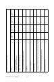
PCA-6185 User’s Manual iv V V V 4 V V V X X V V V 4 V V X X X CPU: Support single Intel® Pentium ® 4 socket 478 processor System chipset: Serverworks GC-SL L2 Cache (128/256/512KB) depends on CPU USB Port VGA: ATI 3D Rage XL VGA RAM: 8MB Single Gigabit 10/100/1000Base-TX Ethernet LAN (Broadcom BCM5703) Dual Gigabit Ethernet LAN (Broadcom BCM5704) SCSI (Adaptec AIC-7902) PCA-6185VG00A1 PCA-6185V00A1 Model PCA-6185 series comparison table X V X V V 4 V V V PCA-6185G20
Product warranty Advantech warrants to you, the original purchaser, that each of its products will be free from defects in materials and workmanship for two years from the date of purchase. This warranty does not apply to any products which have been repaired or altered by persons other than repair personnel authorized by Advantech, or which have been subject to misuse, abuse, accident or improper installation. Advantech assumes no liability under the terms of this warranty as a consequence of such events.
Initial Inspection Before you begin installing your card, please make sure that the following materials have been shipped: •1 socket 478 Pentium 4® processor-based single board computer •1 PCA-6185 startup Manual •1 CD driver utility and manual (in PDF format) •1 FDD cable, P/N: 1701340703 •2 UDMA 100 HDD cables, P/N: 1701400452 •1 Printer (parallel port) cable & COM port cable kit, P/N: 1700060305 •1 Ivory cable for PS/2 keyboard and PS/2 mouse, P/N: 1700060202 •1 USB cable, P/N: 1700100170 (optional) If a
Contents Chapter 1 Hardware Configuration .................................2 1.1 1.2 1.3 Introduction ....................................................................... 2 Features ............................................................................. 3 Specifications .................................................................... 4 1.3.1 1.3.2 1.3.3 1.3.4 1.3.5 1.3.6 1.3.7 1.4 System............................................................................. 4 Memory...................
2.5 2.6 2.7 2.8 2.9 2.10 2.11 VGA Connector (CN7) ................................................... 22 10/100/1000Base-T Ethernet (CN8 and CN34) .............. 23 Serial Ports (CN9: COM1; CN10: COM2) ..................... 23 PS/2 Keyboard and Mouse Connectors (CN11) ............. 24 External Keyboard Connector (CN12)............................ 24 CPU Fan Connector (CN14) ........................................... 24 Front Panel Connectors (CN16, 17, 18, 19, 21&22)....... 25 2.11.1 2.11.2 2.11.3 2.11.
3.6.1 3.6.2 3.6.3 3.6.4 3.7.1 3.7.2 3.7.3 3.7.4 3.7.5 3.7.6 3.8.1 3.8.2 3.8.3 3.8.4 3.9.1 3.9.2 3.9.3 3.9.4 3.9.5 3.9.6 Chapter 4 PCI SVGA Setup ............................................48 4.1 4.2 4.3 Chapter Introduction ..................................................................... 54 Features ........................................................................... 54 Driver Installation ...........................................................
7.8 7.9 7.10 7.11 Using SCSI Disk Utilities ............................................... 77 Installation under Windows NT/Windows 2000............. 77 Windows 2000 Driver setup procedure........................... 78 Windows NT Driver Setup Procedure ............................ 82 Appendix A Programming the Watchdog Timer .............88 A.1 Programming the Watchdog Timer................................. 88 Appendix B Pin Assignments ............................................92 B.1 B.2 B.3 B.
CHAPTER 1 Hardware Configuration This chapter provides background information on the PCA-6185. It will show you how to configure the card to match your application and prepare it for installation into your PC.
Chapter 1 Hardware Configuration 1.1 Introduction The PCA-6185 Series all-in-one industrial grade single CPU card uses Intel's high performance Pentium® 4 processor, together with the ServerWorks' GC-SL chipset. The card features two separate 64-bit PCI-X bus, one for internal deviced and one for external add-on cards. The dual PCIX bus ensures the operation of internal devices not to be influenced by external add-on cards. The PCA-6185 supports Pentium 4 or Celeron CPU with 533 and 400 MHz front side bus.
1.2 Features 1. High performance PCI bus: The PCA-6185 provides three independent PCI buses: one 32-bit, 33 MHz PCI bus and two 64-bit PCI-X buses. The 32-bit bus is used for on-board VGA controller. One of the two high performance PCI-X bus is used for onboard Gigabit Ethernet and SCSI controllers. The other PCI-X bus is available for user's add-on cards through the edge connector.
1.3 Specifications 1.3.1 System • CPU: Intel Pentium® 4 /Celeron processor with 512, 256 or 128 KB L2 cache, up to 3.06 GHz and above, FSB 400/533 MHz • BIOS: Award Flash BIOS, 4 MB • System Chipset: ServerWorks ServerSet GC-SL • Enhanced IDE hard disk drive interface: Supports up to four IDE large hard disk drives or other enhanced IDE devices. Supports PIO mode 4 (16.67 MB/s data transfer rate) and Ultra DMA 33/66/100 (33/66/ 100 MB/s data transfer rate).
1.3.4 VGA interface • On-board PCI VGA controller • Controller: ATI 3D RAGE XL • Display memory: 8 MB SDRAM 1.3.5 Ethernet LAN • Chipset: Broadcom BCM5703 for single GbE and BCM5704 for dual GbE. • Ethernet interface: 10/100/1000 Based - TX • Connection: Onboard RJ-45 connector 1.3.6 Industrial features • Watchdog timer: Can generate a system reset. The watchdog timer is programmable, with each unit equal to one second (63 levels).
1.4 Jumpers and Connectors Connectors on the PCA-6185 board link it to external devices such as hard disk drives and a keyboard. In addition, the board has a number of jumpers used to configure your system for your application. The tables below list the function of each of the board jumpers and connectors. Later sections in this chapter give instructions on setting jumpers. Chapter 2 gives instructions for connecting external devices to your card. Table 1.
Table 1.
1.5 Board Layout: Jumper and Connector Locations Figure 1.
68 pin for Ultra 320 68 pin for Ultra 320 LAN1 LAN2 Figure 1.2: Daughter board layout COM1 LAN 2 USB 0,1 LAN 1 VGA PS/2 mouse & keyboard Figure 1.
Notes: Note1: Shall any incompatibility occur when using add-on cards running at 66MHz PCI or 66 MHz PCI-X, please lower down the PCI bus frequency to 33MHz by setting jumpers on the backplane. You can find how to set the jumpers on the User's Note of the backplane. Note 2: Due to the limitation of the GC-SL chipset, the PCI slot with ID select=AD31 on backplanes will not work. Note 3: The PCA-6185 does not support "Wake-on-LAN" feature.
1.6 Safety Precautions Warning! Always completely disconnect the power cord from your chassis whenever you work with the hardware. Do not make connections while the power is on. Sensitive electronic components can be damaged by sudden power surges. Only experienced electronics personnel should open the PC chassis. Caution! Always ground yourself to remove any static charge before touching the CPU card. Modern electronic devices are very sensitive to static electric charges.
closed for just a few seconds, and then move the jumper back to 1-2 closed. This procedure will reset the CMOS to its default setting. Table 1.
1.7.3 PCI bus type setting selection (JP1) The PCA-6185 CPU card contains a jumper that can set PCI bus type for 33/66 PCI bus or PCI-X, that's depending on add-on cards or backplane setting. Table 1.4: PCI bus type setting selection Function JP1 Jumper setting *PCI only, 33 or 66 MHz depending on add-on cards or backplane setting 1-2 closed PCI-X enabled, PCI/PCI-X mode depending on addon cards or backplane setting.
1.8 System Memory The top-left edge of the PCA-6185 contains three sockets for 184-pin dual inline memory modules (DIMMs). All these sockets accept only 2.5 V registered DDR SDRAM. Registered DIMMs are available in capacities of 128, 256, 512, 1024 or 2048 MB. The sockets can be filled in any combination with DIMMs of any size, with the limitation of the total memory capacity of 4 GB. 1.8.
automatically locked the memory module into the correct position of the DIMM socket. To remove the memory module, just push both handles outward, and the memory module will be ejected by the mechanism in the socket. 1.10 Cache Memory Since the second level (L2) cache has been embedded into the Intel® Pentium® 4 processor, you do not have to take care of either SRAM chips or SRAM modules.
3. Press the lever down. The plate will slide forward. You will feel some resistance as the pressure starts to secure the CPU in the socket. This is normal and will not damage the CPU. 1.12 RAM Module Approval List Module Vendor Module Part No. Chips Memery Size Apacer 77.10312.460 Samsung K4H280838C-TCB0 128M Bytes Apacer 77.10212.460 Samsung K4H280838C-TCB0 256M Bytes Apacer 77.10712.460 Samsung K4H560838C-TCB0 512M Bytes Apacer 77.11243.
1.14 RAID Card Approval List Card Vendor Card Part No. Speed type.
PCA-6185 User’s Manual 18
CHAPTER 2 Connecting Peripherals This chapter tells how to connect peripherals, switches, and indicators to the PCA-6185 board.
Chapter 2 Connecting Peripherals 2.1 Primary (CN1) and Secondary (CN2) IDE Connectors CN2 CN1 You can attach up to four IDE (Integrated Drive Electronics) drives to the PCA-6185’s built-in controller. The primary (CN1) and secondary (CN2) connectors can each accommodate two drives. Wire number 1 on the cable is red or blue and the other wires are gray. Connect one end to connector CN1 or CN2 on the CPU card.
2.2 Floppy Drive Connector (CN3) CN3 You can attach up to two floppy disk drives to the PCA-6185's onboard connector. You can use 3.5" (720 KB, 1.44/2.88 MB) drives. The card comes with a 34-pin daisy-chain drive connector cable. On one end of the cable is a 34-pin flat-cable connector. On the other end are two sets of 34-pin flat-cable connector (usually used for 3.5" drives). The set on the end (after the twist in the cable) connects to the A: floppy drive.
plate. Next, attach the flat-cable connector to CN4 on the CPU card. Wire 1 of the cable is red or blue, and the other wires are gray. Make sure that wire 1 corresponds to pin 1 of CN4. Pin 1 is on the upper right side of CN4. 2.4 USB Ports (CN6/CN26) CN26 There is one onboard USB pin head is available, CN26. The adapter cable has 10-pin connector on one end and a USB connector on the bracket. Please contact with Advantech if USB cable is needed.
2.6 10/100/1000Base-T Ethernet (CN8 and CN34) CN8 and CN34 The PCA-6185 is equipped with one high-performance 64-bit PCI-bus Ethernet interface, which are fully compliant with IEEE 802.3/u 10/100/ 1000 Mbps CSMA/CD standards. They are supported by all major network operating systems. The RJ-45 jacks on the rear plate provide convenient 10/100/1000Base-T RJ-45 operation. 2.7 Serial Ports (CN9: COM1; CN10: COM2) CN9 and CN10 The PCA-6185 offers two serial ports, CN9 as COM1 and CN10 as COM2.
2.8 PS/2 Keyboard and Mouse Connectors (CN11) CN11 The 6-pin mini-DIN connectors (CN11) on the card mounting bracket provides connection to a PS/2 keyboard and a PS/2 mouse, by using the adapter cable (P/N: 1700060202, available from Advantech.) 2.9 External Keyboard Connector (CN12) In addition to the PS/2 mouse/keyboard connector on the PCA-6185's ear plate, there is also an extra onboard external keyboard connector. This gives system integrators greater flexibility in designing their systems. 2.
2.11 Front Panel Connectors (CN16, 17, 18, 19, 21&22) There are several external switches to monitor and control the PCA-6185. 2.11.1 Power LED (CN16) CN16 is a 5-pin connector for the power on LED. Refer to Appendix B for detailed information on the pin assignments. If a PS/2 or ATX power supply is used, the system's power LED status will be as indicated below: Table 2.
2.11.2 External speaker (CN17) CN17 is a 4-pin connector for an extenal speaker. If there is no external speaker, the PCA-6185 provides an onboard buzzer as an alternative. To enable the buzzer, set pins 3-4 as closed 2.11.3 Reset (CN18) Many computer cases offer the convenience of a reset button. Connect the wire from the reset button. 1 2.11.4 HDD LED (CN19) You can connect an LED to connector CN19 to indicate when the HDD is active.
2.11.5 SM Bus Connector (CN29) This connector is reserved for Advantech's SNMP-1000 HTTP/SNMP Remote System Manager. The SNMP-1000 allows users to monitor the internal voltages, temperature and fans from a remote computer through an Ethernet network. CN23 can be connected to CN3 or CN6 of SNMP-1000. Please be careful about the pin assignments, pin 1 must be connected to pin 1 and pin2 to pin 2 on both ends of cable. 2.11.
2.11.8 ATX feature connector (CN20) and soft power switch connector (CN21) The PCA-6185 can support an advanced soft power switch function if an ATX power supply is used. To enable the soft power switch function: 1. Connect the 3-pin plug of the cable to CN20 (ATX feature connector). 2. Connect the power on/off button to CN21. (A momentary type of button should be used.) Note: If you will not be using an ATX power connector, make sure that pins 2-3 of CN20 are closed. Warnings! 1.
CHAPTER 3 Award BIOS Setup This chapter describes how to set the card’s BIOS configuration data.
Chapter 3 Award BIOS Setup 3.1 Introduction Award’s BIOS ROM has a built-in setup program that allows users to modify the basic system configuration. This type of information is stored in battery-backed memory (CMOS RAM) so that it retains the setup information when the power is turned off. 3.1.1 CMOS RAM auto-backup and restore The CMOS RAM is powered by an onboard button cell battery. When BIOS CMOS Setup has been completed, CMOS RAM data is automatically backed up to Flash ROM.
3.2 Entering Setup Turn on the computer and check for the “patch code”. If there is a number assigned to the patch code, it means that the BIOS supports your CPU. If there is no number assigned to the patch code, please contact Advantech’s applications engineer to obtain an up-to-date patch code file. This will ensure that your CPU’s system status is valid. After ensuring that you have a number assigned to the patch code, press to allow you to enter the setup. Figure 3.
3.3 Standard CMOS Setup Choose the “Standard CMOS Features” option from the “Initial Setup Screen” menu, and the screen below will be displayed. This menu allows users to configure system components such as date, time, hard disk drive, floppy drive, display, and memory. Figure 3.
3.4 Advanced BIOS Features The “Advanced BIOS Features” screen appears when choosing the “Advanced BIOS Features” item from the “Initial Setup Screen” menu. It allows the user to configure the PCA-6185 according to his particular requirements. Below are some major items that are provided in the Advanced BIOS Features screen. A quick booting function is provided for your convenience. Simply enable the Quick Booting item to save yourself valuable time. Figure 3.
3.4.1 Boot Seq & Floppy Setup Figure 3.4: Boot sequence 3.4.1.1 First Boot/Second Boot/Third Boot/Other Boot Device You can select the priority of your boot devices. Choices are: Floppy, LS120, HDD-0, SCSI, CDROM, HDD-1, HDD-2, HDD-3, ZIP100, USB-FDD, USB-ZIP, USB-CDROM, USB-HDD, LAN, Disabled. 3.4.1.2 Swap Floppy Drive If the system has two floppy drives, choose "Enable" to assign physical drive B to logical drive A and vise versa. 3.4.1.
3.4.2 Console Redirection Figure 3.5: Console Redirection 3.4.2.1 Console Redirection When enabled, system will attempt to redirect console via COM port. When disabled, system will attempt to redirect console only when keyboard is absent. The baud rate is selectable as 9600, 19200, 38400, 57600, 115200 bps. 3.4.2.2 Agent Connect Via System will detect COM port status automatically. This item is set as "Null" 3.4.2.3 Agent Wait Time (min) Select how many minutes to wait for connection. 3.4.2.
3.4.4 Virus Warning If enabled, a warning message and alarm beep activates if someone attempts to write here. The commands are “Enabled” or “Disabled.” 3.4.5 Hyper-Threading Technology "Enabled" for the Hyper-Threading optimized OS, when used with Intel Pentium 4 CPU with Hyper-Threading technology such as 3.06 GHz. 3.4.6 Quick Power On Self Test Allows the system to skip certain tests while booting. This will decrease the time needed to boot the system. 3.4.
3.4.12 OS Select for DRAM > 64MB This setting allows selecting an OS with greater than 64MB of RAM. Commands are “Non-OS2” or “OS2.” 3.4.13 MPS Version Control for OS It is recommended to keep the setting as default "1.
3.5 Advanced Chipset Features By choosing the “Advanced Chipset Features” option from the “Initial Setup Screen” menu, the screen below will be displayed. This sample screen contains the manufacturer’s default values for the PCA-6185, as shown in Figure 3-4: Note: DRAM default timings have been carefully chosen and should ONLY be changed if data is being lost. Please first contact technical support. Figure 3.6: Advanced chipset features screen 3.5.
3.5.3 Scrubbing The settings are Enabled and Disabled. Scrubbing writes corrected ECC data back into memory. 3.6 Integrated Peripherals Figure 3.7: Integrated peripherals 3.6.1 IDE Funtion Setup 3.6.1.1 On-Chip Primary/Secondary PCI IDE Enable/Disable the primary and secondary IDE HDD interface. 3.6.1.2 IDE Prim/Secondary Master/Slave PIO/UDMA Mode Each channel (Primary and Secondary) has both a master and a slave, making four IDE devices possible.
3.6.2 Super I/O Function Setup 3.6.2.1 Onboard FDC Controller When enabled, this field allows you to connect your floppy disk drives to the onboard floppy disk drive connector instead of a separate controller card. If you want to use a different controller card to connect the floppy disk drives, set this field to Disabled. 3.6.2.2 Onboard Serial Port 1 (3F8H/IRQ4) The settings are Auto 3F8/IRQ4, 2F8/IRQ3, 3E8/IRQ4, 2E8/IRQ3, and Disabled for the on-board serial connector. 3.6.2.
3.6.3.2 USB Keyboard Support Select Enabled if your system contains a Universal Serial Bus (USB) controller and you have a USB keyboard. The choice: Enabled, Disabled. 3.6.4 PWRON After PWR-Fail This field lets you to determine the state that your computer returns after a power failure. If sets to Off, the PC will not boot after a power failure. If sets to On, the PC will restart after a power failure. If sets to Auto, the PC will go back to the previous state before a power failure occurred.
This category allows you to select the type (or degree) of power saving and is directly related to the following modes: 1. HDD Power Down 2. Suspend Mode There are four selections for Power Management, three of which have fixed mode settings. Disable (default) No power management. Disables all four modes Min. Power Saving Minimum power management., Suspend Mode = 1 hr., and HDD Power Down = 15 min. Max. Power Saving Maximum power management., Suspend Mode = 1 min., and HDD Power Down = 1 min.
3.7.4 Video Off In Suspend When you select “Yes”: Video will trun off when computer suspends. When you select “No”: Video will be on when computer suspends. 3.7.5 Soft-Off by PWRBTN If you choose “Instant-Off”, then pushing the ATX soft power switch button once will switch the system to “system off” power mode. You can choose “Delay 4 sec.
3.8.2 Reset Configuration Data Note:This is left “Disabled.” Select “Enabled” to reset Extended System Configuration Data (ECSD) if you have installed a new add-on card and your OS won’t boot and you need to reconfigure. 3.8.3 Resources controlled by: The commands here are “Auto” or “manual.” Choosing “manual” requires you to choose resources from each following sub-menu. “Auto” automatically configures all of the boot and Plug and Play devices but you must be using Windows 95 or above. 3.8.
3.9.2 Current System Temperature This shows you the current system temperature 3.9.3 Current CPU Temperature This shows you the current CPU speed. 3.9.4 Current CPU Fan/System Fan Speed This shows you the current CPU fan/System fan speed. 3.9.5 VCORE This shows CPU core voltage. 3.9.6 VCC3/+5V/+12V/-12V/-5V This shows you the voltage of +3.3V/ + 5V/ +12V 3.10 Load Setup Defaults “LOAD SETUP DEFAULTS” loads the default BIOS settings required by the system for reliable operation. 3.
Enter the current password and press . 3. After pressing (ROM password) or the current password (user-defined), you can change the password stored in the CMOS. The password must be no longer than eight (8) characters. Remember, to enable the password setting feature, you must first select either “Setup” or “System” from the “Advanced BIOS Features” menu. 3.
CHAPTER 4 PCI SVGA Setup The PCA-6185 features an onboard PCI VGA interface. This chapter provides instructions for installing and operating the software drivers on the display driver CD included in your package.
Chapter 4 PCI SVGA Setup 4.1 Before you begin To facilitate the installation of the enhanced display device drivers and utility software, you should read the instructions in this chapter carefully before you attempt installation. The enhanced display drivers for the PCA-6185 board are located on the software installation CD. You must install the drivers and utility software by using the supplied SETUP program for DOS drivers. Note: The files on the software installation CD are compressed.
• Integrates superior video features. These include filtered sealing of 720 pixel DVD content, and MPEG-2 motion compensation for software DVD 4.3 VGA Installation First, insert CD drive. Then follow the Icons for your PCA Series model number. Click on the right driver for the auto-installation. Below take Windows 2000 as an example. Click on "WIN2000", the VGA driver will start installation automatically. You will see the welcome window and ask you to exit all Windows programs.
In the license window, click on "Yes" to continue.
Click on "Yes". The installaion is complete click on "Yes" to restart the system.
PCA-6185 User’s Manual 52
CHAPTER 5 LAN Configuration The PCA-6185 features single or dual 10/100/1000Base-T Ethernet LAN interface. This chapter gives detailed information on Ethernet configuration. It shows you how to configure the card to match your application requirements.
Chapter 5 LAN Configuration 5.1 Introduction The PCA-6185 features single or dual 64-bit gigabit Ethernet networking interace. This interface supports bus mastering architecture and autonegotiation features. Therefore standard twisted-pair cabling with RJ-45 connectors for both 10 Mbps, 100 Mbps, and 1000 Mbps connections can be used. Extensive driver support for commonly-used network systems is also provided. 5.
5.4 Windows NT Drivers (Broadcom 5703/4) Procedure Note : 1. The CD-ROM drive is designated as "D" throughout In the "Windows NT" screen, click on "Start" and select "Settings". Then click on the "Control Panel" icon to select "Net-work". 1 2. In the "Network" window, select the "Adapters" tab. Then click on "Add...".
3. In the "Select Network Adapter" window, click on "Have Disk...". 4. When the "Insert Disk" window appears, insert the utility CD into the CD-ROM drive. The correct file path is D:\Drv_Lan\BROD5703(4)\WindowsNT\Driver. When you have the correct file path, click on "OK". 5. In the "Network" window, select the "Adapters" tab. Under "Network Adapters:", highlight "Gigabit Ethernet Controller". Then click on "Close".
6. In the "Microsoft TCP/IP Properties" window, select the "IP Address" tab. Then select "Specify an IP address". Type in the IP Address and Subnet Mask details. Then click on "OK". 7. In the "Network Settings Change" window, click on "Yes" to restart the computer.
5.5 Windows 2000 Drivers (Broadcom 5703/4) Procedure Note: The CD-ROM drive is designed as "D" throughout this section. 1. In the "Windows 2000" screen, click on " Start" and select " settings". Then click on the " Control Panel" icon to select "system". 2. In the " System Properties" window, select the " Device Manager".
3. In "Device Manager" screen, follow the screen instructions, to click on "Properties". 4. In the following screen, to click on "Update Driver".
5. Click on "Next". 6. Following the highlighted item, and click on "Next". 7.
8. Click on "Have Disk". 9. Key in "D:\Drv_)Lan\BROD5703(4)\Windows2000\Driver", then click on "OK". 10. To highlight the following item, and click "Next".
11. Click "Next". 12. Press Yes to continue the installation 13.
CHAPTER 6 Onboard Security Setup This chapter explains OBS concepts and provides instructions for installing the relevant software drivers. This is done using the driver CD included in your PCA-6185 package.
Chapter 6 Onboard Security Setup 6.1 Introduction Onboard security (OBS) functions monitor key hardware. They help you maintain your system’s stability and durability. The PCA-6185 can monitor 5 sets of system positive voltages, 2 sets of system negative voltages, CPU cooling fan speed, and CPU temperature. The positive system voltage sets which can be monitored include: • CPU core voltage: 1.3 V ~ 3.3 V, according to Intel specifications. • Termination voltage from CPU to chipset: typically 1.5 V.
6.3 Windows XP/2000 Windows XP/2000 Drivers Setup Procedure 1. Insert the driver CD into your system’s CD-ROM drive. In a few seconds, the software installation main menu appears, as shown in the following figure. Click on the “INSTALL” button under the “OBS DRIVERS” heading.
2. Click on OK to install OBS driver 3. After the setup is completed. You can view OBS setting by running this utility. 4. It is recommended that you load the default values for all OBS settings.
CHAPTER 7 SCSI Setup The PCA-6185 features an onboard SCSI interface. This chapter provides basic SCSI concepts and instructions for installing the software drivers with the SCSI driver disks CD included in your package.
Chapter 7 SCSI Setup 7.1 Introduction The PCA-6185 is equipped with an Adaptec AIC-7902 single-chip PCIto-SCSI host adapter which provides a dual channel Ultra 320 multitasking interface between your computer’s PCI bus and SCSI devices (disk drives, CD-ROM drives, scanners, tape backups, removable media drives, etc.). Ultra 320 is a new generation of SCSI technology that expands SCSI performance from 80 MBytes/sec to 320 MBytes/sec.
7.3 SCSI IDs Each device attached to the SCSI bus, as well as the SCSI controller itself, must be assigned a unique SCSI ID number from 0 to 15. A SCSI ID uniquely identifies each SCSI device on the SCSI bus and determines priority when two or more devices are trying to use the SCSI bus at the same time. Refer o the device’s documentation to set the SCSI ID. Here are some general guidelines for SCSI IDs: • For internal SCSI devices, the SCSI ID usually is set by configuring a jumper on the device.
7.4 Terminating the SCSI bus To ensure reliable communication on the SCSI bus, the ends of the SCSI bus must be properly terminated. This is accomplished when the device at the end of the each cable, or the end of the cable itself, has a terminator installed (or enabled). Terminators must be removed, or termination must be disabled, on devices between the ends of each cable.
tems. Run SCSISelect if you need to change or view current settings, or if you would like to run the SCSI disk utilities.
Support Removable Disks BIOS as Fixed Disks2 BIOS Support for Bootable CD_ROM2 BIOS Support for Int 13 Extensions2 Disabled Disabled Boot only All Disks Enabled, Disabled Enabled Enabled, Disabled Enabled Remarks: 1. Setting is valid only if Multiple LUN Support is enabled 2. Settings are valid only if host adapter BIOS is enabled. 7.6 Starting SCSISelect Follow these steps to start SCSISelect: 1. Turn on or restart your system.
7.7 Using SCSISelect Settings To select an option, use the arrow keys to move the cursor to the option, then press ENTER. In some cases, selecting an option displays another meny. You can return to the previous menu at any time by pressing ESC. To restore the original SCSISelect default values, press F6 from the main SCSISelect screen. SCSI Bus Interface Definitions • Host Adapter SCSI ID-(Default: 7) Sets the SCSI ID for the SCSI card.
• Initiate Wide Negotiation-(Default: Yes) When set to Yes, the SCSI card attempts 16-bit data transfer (wide negotiation.) When set to No, the SCSI card uses 8-bit data transfer unless the SCSI device requests wide negotiation. Note: Set Initiate Wide Negotiation to NO if you are using an 8-bit SCSI device that hangs or exhibits other performance problems with 16-bit data transfer rate enabled. • Enable Disconnection-(Default: Yes) When set to Yes, allows the SCSI device to disconnect from the SCSI bus.
system bootup. If this setting disabled, you can still invoke the SCSISelect Utility by pressing after the SCSI card BIOS banner appears. • Extended BIOS Translation for DOS Drives > 1 GByte-(Default: Enabled) When set to Enabled, provides an extended translation scheme for SCSI hard disks with capacities greater than 1 GByte. This setting is necessary only for MS-DOS 5.0 or above; it is not required for other operating systems, such as NetWare of UNIX.
• Support Removable Disks Under BIOS as Fixed Disks—(Default: Disabled) Determines which removable-media drives are supported by the SCSI card BIOS. Choices are as follows: • Disabled— No removable-media drives are treated as hard disk drives. Software drivers are required because the drives are not controlled by the BIOS. • Boot Only—Only the removable-media drive designated as the boot device is treated as a hard disk drive.
7.8 Using SCSI Disk Utilities To access the SCSI disk utilities, follow these steps: 1. Select the SCSI Disk Utilities option from the menu that appears after starting SCSISelect. SCSISelect scans the SCSI bus (to determine the devices installed) and displays a list of all SCSI IDs and the devices assigned to each ID. 2. Use the arrow keys to move the cursor to a specific ID and device, then press Enter. 3. A small menu appears, displaying the options Format Disk and Verify Disk Media.
7.10 Windows 2000 Driver setup procedure 1. In the window 2000 screen, click on “start” and select “setting.” Then click on the “Control Panel” icon to select “System” 2. In the “System properties”, choose “PCI SCSI Bus Controller.
3.
4. Click on “Next” 5.
6. If the SCSI driver is supplied in floppy disk, click on “Floppy disk drives.” Then, click on “Next.” If the SCSI driver is supplied in CD-ROM disk, click on “Specify a location:" then enter "D:\Drv_SCSI\Adaptec7902\Windows\Win2000"” 7. The installation is completed. Click on “Finish.
8. Click on “Yes” to restart the system. 7.11 Windows NT Driver Setup Procedure 1. In the Windows NT screen, click on “Start” and select “Setting.” Then click on the “Control Panel” icon to select “SCSI Adapter.
2. In the SCSI Adapter, choose “Drivers.” Click on “Add” to install SCSI driver. 3. Click on “Have Disk.
4. Click on “Browse” to select the drivers. If the SCSI driver is supplied in floppy disk, choose the directory A:\. 5. Click the SCSI driver, and then click “OK.
6. The installation of SCSI Driver is completed. Click on “OK.
PCA-6185 User’s Manual 86
Appendix A Programming the Watchdog Timer The PPC-123 is equipped with a watchdog timer that resets the CPU or generates an interrupt if processing comes to a standstill for any reason. This feature ensures system reliability in industrial standalone or unmanned environments.
Appendix A Programming the Watchdog Timer A.1 Programming the Watchdog Timer To program the watchdog timer, you must write a program which writes I/ O port address 444 (hex). The output data is a time interval value. The value range is from 01 (hex) to 3E (hex), and the related time interval is from 1 sec. to 62 sec. Data Time Interval 01 1 sec. 02 2 sec. 03 3 sec. 04 4 sec. • • • • • • 3E 62 sec.
The following example shows how you might program the watchdog timer in BASIC: 10 REM Watchdog timer example program 20 OUT &H444, data REM Start and restart the watchdog 30 GOSUB 1000 REM Your application task #1, 40 OUT &H444, data REM Reset the timer 50 GOSUB 2000 REM Your application task #2, 60 OUT &H444, data REM Reset the timer 70 X=INP (&H43) REM, Disable the watchdog timer 80 END 1000 REM Subroutine #1, your application task • • • • • • 1070 RETURN 2000 REM Subroutine #2, your
PCA-6185 User’s Manual 90
Appendix Pin Assignments B
Appendix B Pin Assignments B.1 IDE Hard Drive Connector (CN1, CN2) 1 3 37 39 2 4 38 40 Table B.
B.2 Floppy Drive Connector (CN3) 33 31 3 1 34 32 4 2 Table B.
B.3 Parallel Port Connector (CN4) 13 12 2 1 26 25 15 14 Table B.
B.4 USB Connector (CN6) 1 2 3 4 5 6 7 8 9 10 Table B.4: USB1/USB2 connector (CN6) Pin USB1 Signal Pin 1 +5 V 6 2 UV7 3 UV+ 8 4 GND 9 5 Chassis GND 10 USB2 Signal +5 V UVUV+ GND N/C B.5 VGA Connector (CN7) 5 1 10 6 15 Table B.
B.6 Keyboard and Mouse Connnector (CN11) 6 5 4 3 2 1 Table B.6: Keyboard and mouse connector (CN11) Pin Signal 1 KB DATA 2 MS DATA 3 GND 4 VCC 5 KB CLOCK 6 MS CLOCK B.7 External Keyboard Connector (CN12) Table B.
B.8 CPU Fan Power Connector (CN14) 1 Table B.8: CPU fan power connector (CN14) Pin Signal 1 GND 2 +12 V 3 Detect B.9 Power LED (CN16) You can use an LED to indicate when the CPU card is on. Pin 1 of CN16 supplies the LED's power, and Pin 3 is the ground. Table B.
B.10 External Speaker Connector (CN17) The CPU card has its own buzzer. You can also connect it to the external speaker on your computer chassis. Table B.10: External speaker (CN17) Pin Function 1 +5 VCC 2 GND 3 Internal buzzer 4 Speaker out B.11 Reset Connector (CN18) 1 Table B.
B.12 HDD LED Connector (CN19) 1 Table B.12: HDD LED connector (CN19) Pin Signal 1 Vcc(LED+) 2 LED0 (LED-) B.13 ATX Feature Connector (CN20) 1 Table B.
B.14 ATX Soft Power Switch (CN21) 1 Table B.14: ATX soft power switch (CN21) Pin Signal 1 3VSB 2 PWR-BTN B.15 SM Bus Connector (CN29) 1 Table B.
B.16 System I/O Ports Table B.16: System I/O ports Addr.
B.18 Interrupt Assignments Table B.
B.20 PCI Bus Map Table B.
PCA-6185 User’s Manual 104