ES-3115 G/R/C/S/V - XA 15" Open-Frame LCD Monitor with Anti-glare Glass/ Resistive / Capacitive / 3mm SAW / 6 mm Vandal Proof SAW Touchscreens
Copyright Notice Advantech Co., Ltd copyrights this document. All rights are reserved. Advantech Co., Ltd. reserves the right to make improvements to the products described in this manual at any time. Specifications are thus subject to change without notice. No part of this manual may be reproduced, copied, translated, or transmitted in any form or by any means without the prior written permission of Advantech Co., Ltd. Information provided in this manual is intended to be accurate and reliable.
Packing List Before installing your equipment, make sure that the following materials have been received: • ES-3115G-XA or ES-3115R-XA or ES-3115C-XA or ES-3115S-XA or ES-3115V-XA • Accessory box, including: - CD for ES-3115G/R/C/S/V-XA Driver - 12V DC Power adapter - 2-wire Power cord for adapter - 1.8 m VGA cable - 1.8 m RS-232 cable for If any of these items are missing or damaged, contact your distributor or sales representative immediately. Additional Information and Assistance 1.
Safety Instructions 1. 2. 3. 4. 5. 6. 7. 8. 9. 10. 11. 12. 13. 14. 15. Read these safety instructions carefully. Keep this User's Manual for later reference. Disconnect this equipment from any AC outlet before cleaning. Use a damp cloth. Do not use liquid or spray detergents for cleaning. For plug-in equipment, the power outlet socket must be located near the equipment and must be easily accessible. Keep this equipment away from humidity. Put this equipment on a reliable surface during installation.
Contents Chapter 1 Introduction ................................................... 1 1.1 1.2 1.3 1.4 Introduction...................................................................... 2 Product Features ............................................................. 3 VGA Signal ....................................................................... 4 LCD Specification............................................................ 5 1.4.1 LCD Specification ................................................. 5 1.
Figures Figure 2-1: Figure 3-1: Figure 3-2: Figure 3-3: Figure 3-4: Figure 3-5: Figure 3-6: Figure 3-7: Figure 3-8: Figure 3-9: Figure 3-10: Figure 3-11: Figure 3-12: Figure 3-13: Rear view of the ES-3115 C/R/S/SV-XM..............................………16 Dimensions of the ES-3115 C/R-XM .............................................. 23 ES-3115 C/R-XM Dimensions of cutoff and panel mounting holes ..........................................................................…..
CHAPTER General Information This chapter includes: • Introduction • Product Features 1
1.1 Introduction This product, LCD touch monitor, is mainly focused on Kiosk market or Human Machine Interface (HMI). It is a core module for Kiosk application. The LCD touch monitor supports direct VGA analog signal inputs, which make it more compatible and adaptable to connect to computers widely used in the current market. The LCD touch monitor just provides a steel open frame so that Kiosk providers can design their specific IDs to demonstrate their own Kiosk application.
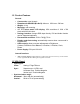
1.2 Product Features General • • • • • • • • • • Construction: steel chassis Dimensions for G/R/C/S/V (W x H x D): 414 mm x 322.2 mm x 500 mm Weight: 4.1 kg Mounting: rear mounting 15" TFT active matrix LCD display: XGA resolution of 1024 x 768 pixels with 262144 colors. Analogy interface: Accepts RGB input directly. DVI and Audio function can be supported optionally Recommend resolution: 1024 x 768 @ 75 Hz. Display mode Auto tuning: automatically execute when a new mode is implemented.
• Display mode support: Item Resolution H Freq.(kHz) V Freq.(Hz) Note 1 640x400@70 31.469 70.087 VGA 2 640x480@60 31.469 59.940 VESA 3 640x480@66 35.000 66.667 MAC 4 640x480@72 37.861 72.809 VESA 5 640x480@75 37.500 75.000 VESA 6 720x400@70 31.469 70.087 TEXT 7 800x600@56 35.156 56.250 VESA 8 800x600@60 37.879 60.317 VESA 9 800x600@72 48.077 72.188 VESA 10 800x600@75 46.875 75.000 VESA 11 832x624@75 49.107 75.087 MAC 12 1024x768@60 48.363 60.
1.4 LCD Specification 1.4.1 LCD Specification DF-14H-20P-1.25H (Hirose) or CWY20G-A0D1T (PTWO) Pin No. Symbol Description Display Type 15” XGA TFT LCD Active Area (mm) 304.128 X 228.096 Resolution Dot Pitch (mm) Supply Voltage (Panel) Viewing angle (v,h) Contrast Luminance (cd/m2) 1024 X 768 0.297 X 0.
1.4.2 LCD pin definition M150XN07 pin definition is shown in the table below. 1 2 3 4 5 6 7 8 9 10 11 12 13 14 15 16 17 18 19 20 VDD VDD VSS VSS Rin0Rin0+ VSS Rin1Rin1+ VSS Rin2Rin2+ VSS ClkINClkIN+ VSS Rin3Rin3+ VSS NC Power Supply, 3.3V (typical) Power Supply, 3.
1.5 Touchscreen Specification 1.5.1 ES-3115C (Capacity) • • • • • • • Type: 3M Touch Systems-Microtouch capacity touch screen Resolution: 1024 x 1024 Light Transmission: 85% Touch Life Cycle: 225 million Controller: RS-232 interface Communication speed: up to 19.2K baud. Power consumption: +5 V @ 100 mA 1.5.
1.6 External AC Power Adapter • Output: 12Vdc/4.0A • Input: 100 ~ 240 Vac, 47 ~ 63 Hz, 1.2A • Efficiency: better than 84% under maximum load. MTBF: 50,000 hr at 25°C • 1.
CHAPTER System Setup • Introduction • Preparing for First-time Use • I/O arrangement • Installation Procedure • OSD Control • Enabling the Touchscreen 2
2.1 Introduction This chapter describes basic features and procedures for using the Open-frame LCD monitor. Topics covered include the system installation, OSD control, Touchscreen, and so on. 2.2 Preparing for First-time Use Before you start to set up the ES-3115 LCD Monitor, You should have at least the following items ready in your accessory box: • 12V DC Power adapter • 2-wire Power cord for adapter • 1.8m VGA cable • 1.
2.4 Installation Procedure The ES-3115 can only be powered by an AC electrical outlet adapter (90 ~ 240 volts). Be sure to always handle the power cord and power adapter by holding the plug ends only. 1. Make sure that the system power is turned off. 2. Connect the VGA cable and RS-232 cable between the ES-3115 and your PC system. 3. Plug the 2-way power cord to the power adapter. Plug the adapter cable to the DC 12V jack of ES-3115. 4. Connect the 2-pin male plug of the power cord to an electrical outlet.
2. [Menu] (Menu KEY) is designated for Menu/Enter function depending on the selected item. Pressing [Menu] can invoke OSD menu. After that, [Menu] is also an entry key. 3. [← /↑] (INC KEY) is designated for selection function in up direction in OSD menu and also to increase the value on selected function. 4. [→ /↓] (DEC KEY) is designated for selection function in down direction in OSD menu and also to decrease the value on selected function. 5.
noise on the screen while adjust the Clock. Press” INC” or “DEC” to adjust the parameter Adjusts the video distortion.
and etc. ES-3115C-XA provides 1 CD kit which contain capacitive driver. It enables you to use the capacitive touchscreen with applications running in Windows environments. You can run Windows programs and use touch input without any program modification. 1. Make sure the RS-232 cable is properly connected. program cannot configure the touchscreen without it. The Setup 2. Insert the CD Kit into your PC system's CD drive. 3. Change to the \3M Microtouch\ directory. Click the SETUP.EXE installation program.
The SAW touchscreen of ES-3115S-XA is patented technology available from Elotouch System. Its tough, scratch-resistant and wear-resistant feature is an ideal choice for unattended kiosks and POI applications in public places like train stations, airports, malls, supermarket, and etc. ES-3115V-XA provides 1 CD kit which contain SAW driver. It enables you to use the resistive touchscreen with applications running in Windows environments.
carefully when answering questions to complete the installation.
CHAPTER 3 Specification • Introduction • Mechanical Dimension • Cut-out Dimensions for Rear Mounting • Mounting Guide • Exploded Diagram • Electrical Block Diagram • ADC Board • DC to DC Power Board • DC to AC Inverter • Touchscreen Control Board
3.1 Introduction The mechanical design concept of ES-3115 G/ R/C/ S/ V -XA follows easy assembling, easy maintenance principles. Two main metal parts are used to support PCB, LCD panel, and touch screen. Basically, front frame and back frame form a space to contain all parts of LCD touch monitor. The back frame metal plate are used to mount PCB boards and LCD panel, front metal frame is used to mount the Touchscreen.
3.2 Mechanical Dimension Mechanical Dimension of ES-3115G/R/C/S/V-XA 414.00 50.00 286.80 322.20 305.40 220.00 160.50 396.00 300.00 210.50 278.40 377.
3.3 Cut-out Dimension for ES-3115 G/R/C/S/V-XA Rear Mounting To construct a suitable panel, refer to the following cutout & elongated holes dimension diagram. 306.00 Display opening size Figure 3-3: ES-3115 G/R/C/S/V–XA dimensions of cut-off. 229.
3.4 Mounting guide To mount the ES-3115G/R/C/S/V-XA into a panel or kiosk: 1. Build 8 screw studs along the four sides of the cut out opening based on the dimension given on the drawing above. 2. There are ten elongated holes located along the four sides of the open frame monitor. Mount the open frame LCD monitor on by aligning the screw studs with the elongated hole. 3. Tighten the screw stud with hex nut and make sure it is stable. Note: The screw stud should not be less than M4 and 5mm in height.
3.5 Mounting guide 3.5.
3.5.
3.6 Electrical Block Diagram According to the product idea, 15"” LCD panel and touchscreen are the basic two components in this product. Besides, in order to reduce the depth of LCD touch monitor and solve cooling problem at the same time, a DC input is designed to remove the AC switching power supply. An AC switching power adapter of full range is used to provide DC voltage of the monitor. The LCD touch monitor is constructed based on steel open frame architecture.
3.7 ADC Board The ADC board is used to convert RGB signal to LCD digital signal and send to LCD panel to display.
3.8 DC to AC Inverter The DC/AC inverter is used to provide the power to LCD backlight.
3.9 Touch Screen Control Board Except ES-3115G-XA, all other ES-3115 series provide various touch screen with different technical.
ES-3115S-XA and ES-3115V-XA used the ELO’s Surface Wave touch screen as below: Figure 3-13: Locating connector of ES-3115S and ES-3115V control board