
User's Manual

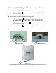

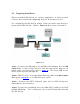

Table Of Contents
- _
- Chapter 1. Introduction
- 1.1 Introducing the EKI-6311g
- 1.2 Product Features
- 1.3 Package Contents
- 1.4 System Requirements
- 1.5 Inline Power Injector (PoE)
- Chapter 2. Installation and Basic Configuration
- 2.1 Before You Start
- 2.2 Locate the EKI-6311g and Inline Power Injector Ports
- 2.3 Preparing Installation
- 2.4 Basic Configuration
- 2.4.1 Logging into the Web Interface
- 2.4.2 Basic Configuration Steps
- 2.4.3 Set Operating Mode, IP Address, Subnet Mask, Default Route IP, DNS Server IP of EKI-6311G
- 2.4.4 Set Wireless SSID for Wireless Interface
- 2.4.5 Set Wireless Encryption for Wireless Interface
- 2.4.6 Change Supervisor Account & Password
- 2.4.7 pgrade the Firmware
- Chapter 3. Network Topologies
- Chapter 4. All function on Device
- Chapter 5. Specifications
- Chapter 6. Default Settings
- Chapter 7. Regulatory Compliance Information

2.3 Preparing Installation
Before installing EKI- 6311g for outdoor applicat ion or hard- to- reach
location, we recom m end configuring and test all t he devices first.
For configuring t he EKI - 6311g, please follow t he quick st eps below t o
power up t he EKI - 6311g. Refer to Figure 2 - 4 for st eps 1 t hrough 5.
Figure 2 - 4
St ep1 : Connect t he DC plug of the AC/ DC power adapter int o t he D C
I nput Port of I nline Power I nj ect or and t he wall-m ount plug int o a
power outlet or power st rip ( refer to
page 6 ). The Power LED on t he
I nline Power I nj ect or will light up.
St ep2 : Run the cross- over t ype uplink Ethernet cable from Dat a I nput
Port ( refer t o
page 6 ) to t he Ethernet port on PC.
St ep3 : Connect t he CAT 5 Ethernet cable int o the EKI - 6311g unit.
Hand t ight ens the connect or.
St ep4 : Connect t he rem aining end of the 30m CAT 5 cable into t he PoE
labeled AP/ Bridge. This is the power side of t he PoE that will power up
the EKI - 6311g.
9