
User's Manual
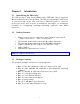

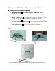


Table Of Contents
- _
- Chapter 1. Introduction
- 1.1 Introducing the EKI-6311g
- 1.2 Product Features
- 1.3 Package Contents
- 1.4 System Requirements
- 1.5 Inline Power Injector (PoE)
- Chapter 2. Installation and Basic Configuration
- 2.1 Before You Start
- 2.2 Locate the EKI-6311g and Inline Power Injector Ports
- 2.3 Preparing Installation
- 2.4 Basic Configuration
- 2.4.1 Logging into the Web Interface
- 2.4.2 Basic Configuration Steps
- 2.4.3 Set Operating Mode, IP Address, Subnet Mask, Default Route IP, DNS Server IP of EKI-6311G
- 2.4.4 Set Wireless SSID for Wireless Interface
- 2.4.5 Set Wireless Encryption for Wireless Interface
- 2.4.6 Change Supervisor Account & Password
- 2.4.7 pgrade the Firmware
- Chapter 3. Network Topologies
- Chapter 4. All function on Device
- Chapter 5. Specifications
- Chapter 6. Default Settings
- Chapter 7. Regulatory Compliance Information

2.2 Locate the EKI-6311g and Inline Power Injector Ports 2.2 Locate the EKI-6311g and Inline Power Injector Ports
► I nt erface on t he EKI - 6 3 1 1 g Unit ► I nt erface on t he EKI - 6 3 1 1 g Unit
Et h er net Por t 1 : for connecting t he 30m RJ-45 CAT-5 Et h er net Por t 1 : for connecting t he 30m RJ- 45 CAT-5
Ethernet cable.
► I nt e rfa ce on t he I nline Pow er I nj e ctor
Da t a I nput Por t 2 : for connecting cross- over Ethernet Cable
to PC or straight Ethernet cable to Hub Swit ch Rout er .
DC I nput Port 3 : power adapter 48V, 0.38A DC input.
Pow er & Da t a Out put Por t 4 : for connecting t he 30m RJ-45
CAT- 5 Et hernet Cable.
Grounding Port 5 : for connecting grounding wire.
Device
POE picture1 POE picture2
5
4
2
3
Figure 2 - 1
Pow er and D a t a I nt e rfa ce locat ion on t he PoE de noted by num bers 1 - 5 .
1
7