
User's Manual

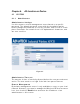


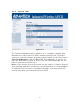


Table Of Contents
- _
- Chapter 1. Introduction
- 1.1 Introducing the EKI-6311g
- 1.2 Product Features
- 1.3 Package Contents
- 1.4 System Requirements
- 1.5 Inline Power Injector (PoE)
- Chapter 2. Installation and Basic Configuration
- 2.1 Before You Start
- 2.2 Locate the EKI-6311g and Inline Power Injector Ports
- 2.3 Preparing Installation
- 2.4 Basic Configuration
- 2.4.1 Logging into the Web Interface
- 2.4.2 Basic Configuration Steps
- 2.4.3 Set Operating Mode, IP Address, Subnet Mask, Default Route IP, DNS Server IP of EKI-6311G
- 2.4.4 Set Wireless SSID for Wireless Interface
- 2.4.5 Set Wireless Encryption for Wireless Interface
- 2.4.6 Change Supervisor Account & Password
- 2.4.7 pgrade the Firmware
- Chapter 3. Network Topologies
- Chapter 4. All function on Device
- Chapter 5. Specifications
- Chapter 6. Default Settings
- Chapter 7. Regulatory Compliance Information

4 .1 .4 St a t us
Figure 4 - 4
You can use the Status screen t o see t he connect ion stat us for t he LAN
and Wireless LAN interfaces. I t also displays system up tim e and
firm ware version.
The following item s are included in t his screen:
SYSTEM I N FORM ATI ON - Displays MAC address, Syst em tim e,
Current firm ware version and operat ion m ode.
LAN I NFORM ATI ON - Displays I P sett ings of LAN port, including I P
Address and Subnet Mask.
W I RELESS I NFORM ATI ON - Displays wireless inform at ion, including
SSI D, channel, Security stat us, and RF out put power.
SYSTEM I N FORM ATI ON - Displays t he system up t im e, the Wireless
CPE's firm ware version, and t he serial num ber.
25