
User's Manual

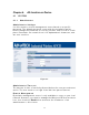


Table Of Contents
- _
- Chapter 1. Introduction
- 1.1 Introducing the EKI-6311g
- 1.2 Product Features
- 1.3 Package Contents
- 1.4 System Requirements
- 1.5 Inline Power Injector (PoE)
- Chapter 2. Installation and Basic Configuration
- 2.1 Before You Start
- 2.2 Locate the EKI-6311g and Inline Power Injector Ports
- 2.3 Preparing Installation
- 2.4 Basic Configuration
- 2.4.1 Logging into the Web Interface
- 2.4.2 Basic Configuration Steps
- 2.4.3 Set Operating Mode, IP Address, Subnet Mask, Default Route IP, DNS Server IP of EKI-6311G
- 2.4.4 Set Wireless SSID for Wireless Interface
- 2.4.5 Set Wireless Encryption for Wireless Interface
- 2.4.6 Change Supervisor Account & Password
- 2.4.7 pgrade the Firmware
- Chapter 3. Network Topologies
- Chapter 4. All function on Device
- Chapter 5. Specifications
- Chapter 6. Default Settings
- Chapter 7. Regulatory Compliance Information

3.1 Wireless Client Bridge-to-Central Wireless Bridge
Figure 3-2
Refer to Figure 3- 2 for t he following setup.
N ot e:
The EKI - 6311G AP m ode is the Central Wireless Bridge and
EKI -6311G CB is the Wireless Client Bridge
St ep 1 Set the EKI- 6311G AP m ode t o perform a bridge ( exa m ple : I P
addre ss: 1 9 2 .1 6 8 .1 .1 ) .
St ep 2 Set Wireless param et ers on the AP t o: Channe l ( 1 ) and SSI D
( EKI - 6 3 1 1 G)
St ep 3 Set the EKI- 6311G CB to function in the bridge m ode ( bridge I P
addre ss: 1 9 2 .1 6 8 .1 .2 4 1 ).
St ep 4 Set Wireless param et ers on t he EKI - 6311G CB t o: Cha nne l ( 1 )
and SSI D ( EKI - 6 3 1 1 G) , and t hese param et ers m ust be t he sam e wit h
COU.
St ep 5 Left side subnet is transparent to t he right side.
St ep 6 DHCP server assign I P address t o PC1 and PC2.
21