
User's Manual

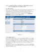

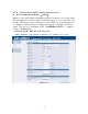


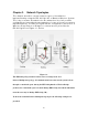
Table Of Contents
- _
- Chapter 1. Introduction
- 1.1 Introducing the EKI-6311g
- 1.2 Product Features
- 1.3 Package Contents
- 1.4 System Requirements
- 1.5 Inline Power Injector (PoE)
- Chapter 2. Installation and Basic Configuration
- 2.1 Before You Start
- 2.2 Locate the EKI-6311g and Inline Power Injector Ports
- 2.3 Preparing Installation
- 2.4 Basic Configuration
- 2.4.1 Logging into the Web Interface
- 2.4.2 Basic Configuration Steps
- 2.4.3 Set Operating Mode, IP Address, Subnet Mask, Default Route IP, DNS Server IP of EKI-6311G
- 2.4.4 Set Wireless SSID for Wireless Interface
- 2.4.5 Set Wireless Encryption for Wireless Interface
- 2.4.6 Change Supervisor Account & Password
- 2.4.7 pgrade the Firmware
- Chapter 3. Network Topologies
- Chapter 4. All function on Device
- Chapter 5. Specifications
- Chapter 6. Default Settings
- Chapter 7. Regulatory Compliance Information

Chapter 3. Network Topologies
This chapter describes several com m on t ypes of installat ions
im plem ent ed by using the EKI - 6311g’s line of Out door Wireless System .
This is by no m eans intended t o be an exhaustive list of all possible
configurations, but rat her shows exam p l es o f som e of t h e m o r e co m m o n
im plem ent at ions. The EKI - 6311g CB can be configured to function as a
Wireless Client Rout er or Bridge to a central access point like the
EKI -6311g AP see Figure 3- 1 below.
Figure 3-1
The EKI-6311g CB performs in either router or bridge mode. In a
Point-to-Multipoint topology, all communication between network systems is done
through a centralized agent. Among the EKI-6311g Outdoor Wireless Bridge
products, the centralized agent is Central Bridge (EKI-6311g AP) and the individual
network notes may be Bridge (EKI-6311g CB ).
To show the available Point-to-Multipoint topologies, the following examples are
provided.
20