
User's Manual
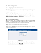

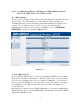
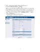


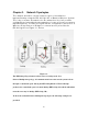
Table Of Contents
- _
- Chapter 1. Introduction
- 1.1 Introducing the EKI-6311g
- 1.2 Product Features
- 1.3 Package Contents
- 1.4 System Requirements
- 1.5 Inline Power Injector (PoE)
- Chapter 2. Installation and Basic Configuration
- 2.1 Before You Start
- 2.2 Locate the EKI-6311g and Inline Power Injector Ports
- 2.3 Preparing Installation
- 2.4 Basic Configuration
- 2.4.1 Logging into the Web Interface
- 2.4.2 Basic Configuration Steps
- 2.4.3 Set Operating Mode, IP Address, Subnet Mask, Default Route IP, DNS Server IP of EKI-6311G
- 2.4.4 Set Wireless SSID for Wireless Interface
- 2.4.5 Set Wireless Encryption for Wireless Interface
- 2.4.6 Change Supervisor Account & Password
- 2.4.7 pgrade the Firmware
- Chapter 3. Network Topologies
- Chapter 4. All function on Device
- Chapter 5. Specifications
- Chapter 6. Default Settings
- Chapter 7. Regulatory Compliance Information

2.4 Basic Configuration
2 .4 .1 Logging int o t h e W e b I nterface
The EKI - 6311G support s access t o t he configuration system through t he
use of an HTTP I nterface.
► W eb Con figura t ion
Before configuring EKI - 6311G, the user needs to know the I P Address
assigned to t he unit . When shipped from the factory, t he I P Address
1 9 2 .1 6 8 .1 .1 was assigned t o t he EKI -6311G by default. To st a rt a
w e b conne ct ion, use ht t p:/ / 1 9 2 .1 6 8 .1 .1
► W eb Acce ss Procedure s
Once you ident ify the I P Address assigned to EKI - 6311G, use web
browser t o configure EKI- 6311G through the HTTP I nt erface. The
following procedure explains how t o configure each it em .
St ep1 : Open your browser and ent er t he I P Address
St ep2 : Press < EN TER> key and t he EKI - 6311G Login screen appears
as shown in Figure 2 - 3 .
Figure 2 - 3
St ep3 : Enter “ a dm in” in the User na m e. Enter “ a dm in” in the
Passw or d fields, and click Log I n to enter the web configurat ion
user interface screen as shown below.
11