EKI-6311G IEEE 802.
► Contents Chapter 1. Introduction ...................................................................................4 1.1 Introducing the EKI-6311g ............................................................4 1.2 Product Features ...........................................................................4 1.3 Package Contents .........................................................................4 1.4 System Requirements ...................................................................5 1.
4.5.1 Agent Settings ......................................................................36 4.6 EXIT ..............................................................................................36 Chapter 5. Specifications ..............................................................................37 Chapter 6. Default Settings ...........................................................................40 6.1 SYSTEM........................................................................................
Chapter 1. 1.1 Introduction Introducing the EKI-6311g The EKI - 6311g is fully int eroperable wit h I EEE 802.11b/ g com pliant Out door Wireless Last- m ile product . The EKI - 6311g operat es in AP m ode or rem ot e bridge m ode, and connect s t o EKI - 6311g CB t o const ruct point- t o- point as w ell as point- t o- m ult ipoint t opologies, for m axim um flexibilit y in configuring building- t o- building net works and WI SP funct ions. 1.
1.4 System Requirements I nst allat ion of t he EKI - 6311g Out door Wireless Access Point unit requires t he following: 1. A Windows- based PC/ AT com pat ible com put er ( PC syst em requirem ent:better than PIII 800 or other 100% compatible equipment , OS: windows 2000/XP ) or Et hernet dat a device wit h an available RJ- 45 Et hernet port t o run t he configurat ion program or wit h TCP/ I P connect ion t o t he Et hernet net work. 2.
Chapter 2. Installation and Basic Configuration This chapt er describes t he procedures of inst alling t he EKI - 6311g. 2.1 Before You Start Aft er unpacking t he syst em , m ake sure t he following it em s are present and in good condit ion. Refer t o below pict ures for product im age. 1 . EKI - 6311g Out door Wireless Access Point / Client Bridge unit 2 . 100~ 240VAC, 50~ 60Hz AC t o 48V/ 0.375A DC swit ching adapt er 3 . I nline Power I nj ect or ( PoE) 48VDC, 0.375A 4 . Grounding wire 1.8m 5 .
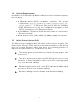
2.2 Locate the EKI-6311g and Inline Power Injector Ports ► I n t e r fa ce on t he EKI - 6 3 1 1 g Un it Et h e r n e t Por t 1 : for connect ing t he 30m RJ- 45 CAT- 5 Et hernet cable. ► I n t e r fa ce on t h e I n lin e Pow e r I nj e ct or D a t a I n pu t Por t 2 : for connect ing cross- over Et hernet Cable t o PC or st raight Et hernet cable t o Hub Swit ch Rout er . D C I n pu t Por t 3 : power adapt er 48V, 0.38A DC input .
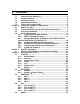
► M ou n t EKI - 6 3 1 1 G on A W a ll/ M a st The EKI - 6311G can be m ount ed on t he wall, you can use t he Wall Mount kit t o m ount t he EKI - 6311G as shown in Figu r e 2 - 2 . Figur e 2 - 2 You can also m ount t he EKI - 6311G t o t he m ast as shown in Figu r e 2 - 3 .
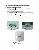
2.3 Preparing Installation Before inst alling EKI - 6311g for out door applicat ion or hard- t o- reach locat ion, we recom m end configuring and t est all t he devices first . For configuring t he EKI - 6311g, please follow t he quick st eps below t o power up t he EKI - 6311g. Refer t o Figu r e 2 - 4 for st eps 1 t hrough 5.
When t he EKI - 6311g receives power over t he Et hernet cable, t he EKI - 6311g will st art it s boot up sequence. You can configure t he EKI - 6311g via HTML browser, such as Microsoft I nt ernet Explorer or Net scape Navigat or from a rem ot e host or PC.
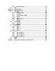
2.4 2 .4 .1 Basic Configuration Loggin g in t o t h e W e b I n t e r fa ce The EKI - 6311G support s access t o t he configurat ion syst em t hrough t he use of an HTTP I nt erface. ► W e b Con figur a t ion Before configuring EKI - 6311G, t he user needs t o know t he I P Address assigned t o t he unit . When shipped from t he fact ory, t he I P Address 1 9 2 .1 6 8 .1 .1 was assigned t o t he EKI - 6311G by default . To st a r t a w e b con n e ct ion , u se h t t p:/ / 1 9 2 .1 6 8 .1 .
Figur e 2 - 4 ► W e b Con figur a t ion St r uct u r e The web configurat ion user int erface shown above in Figu r e 2 - 4 is grouped int o a t ree st ruct ure, and cont ains t he following set t ings or inform at ion.
● ● ● ● ACL ACL ACL ACL for for for for Wi- fi Wi- fi Wi- fi Wi- fi 1 2 3 4 ▽ SNMP ● Agent Set t ings ▽ EXI T Move t hrough t he t ree by clicking on an icon t o expand or collapse t he t ree. The nodes on t he t ree represent web pages t hat allow viewing and m odifying t he param et ers. 2 .4 .2 Ba sic Con figur a t ion St e ps Note: All setting changing must Re boot the device after click Apply This sect ion describes t wo- st ep BASI C configurat ion procedures t o set up EKI - 6311G.
2 .4 .3 Se t Ope r a t in g M ode , I P Addr e ss, Su bn e t M a sk , D e fa u lt Rou t e I P, D N S Se r ve r I P of EKI - 6 3 1 1 G ► LAN Se t t in gs These are t he set t ings of t he LAN ( Local Area Net work) int erface for t he Access Point . The Access Point 's local net work ( LAN) set t ings are configured based on t he I P Address and Subnet Mask assigned in t his sect ion. The I P address is also used t o access t his Web- based m anagem ent int erface.
► I P Addr e ss The I P address of t he AP on t he local area net work. Assign any unused I P address in t he range of I P addresses available for t he LAN. For exam ple, I P address: 192.168.1.100. ► Su bn e t M a sk The subnet m ask of t he local area net work. ► Ga t e w a y The I P address of t he rout er on t he local area net work. ► D N S Se r ve r This ent ry is opt ional. Ent er a DNS Server for t he local net work.
2 .4 .4 Se t W ir e le ss SSI D for W ir e le ss I n t e r fa ce ► W ir e le ss N e t w or k N a m e (SSI D ) When you are brow sing for available wireless net works, t his is t he nam e t hat will appear in t he list ( unless Visibilit y St at us is set t o invisible, see below) . This nam e is also referred t o as t he SSI D. For securit y purposes, it is highly recom m ended t o change from t he pre- configured net work nam e.
2 .4 .5 Se t W ir e le ss En cr ypt ion for W ir e le ss I n t e r fa ce The EKI - 6311G support s 64- bit and 128- bit WEP encrypt ion. For 6 4 - bit WEP encrypt ion, an encrypt ion key is 10 hexadecim al charact ers ( 0- 9 and A- F) or 5 ASCI I charact ers. For 1 2 8 - bit WEP encrypt ion, an encrypt ion key is 26 hexadecim al charact ers or 13 ASCI I charact ers. Modify t he WEP encrypt ion param et ers on t he web page “ / W I RELESS/ W i- Fi 1 / W ir e le ss SECURI TY”.
2 .4 .6 Ch a n ge Su pe r visor Accou n t & Pa ssw or d Ent er t he SYSTEM > Adm in ist r a t or page. Figu r e 2 - 8 below shows t he SYSTEM / Adm in ist r a t or page. Figur e 2 - 8 ► AD M I N PASSW ORD Ch a n gin g Ent er current password in t he SYSTEM / Adm in ist r a t or / Pa ssw or d Se t t in g Cur r e n t Pa ssw or d field. Ent er new password in t he “ PASSW ORD a n d Re - t ype Pa ssw or d” field for changing new password. Then and click APPLY and r e boot t he device.
2 .4 .7 ► pgr a de t h e Fir m w a r e Upda t e t h e Fir m w a r e Ent er t he SYSTEM > FI RM W ARE page as shown in Figu r e 2 - 9 t o upgrade EKI - 6311G. Here, user m ust select which file you want t o upgrade it ( Pr ogr a m im a ge ) , t hen click APPLY but t on t o st art t he upgrade process. H int : I t t akes about 10 m in, t o com plet e t he rest art process.
Chapter 3. Network Topologies This chapt er describes several com m on t ypes of inst allat ions im plem ent ed by using t he EKI - 6311g’s line of Out door Wireless Syst em . This is by no m eans int ended t o be an exhaust ive list of all possible configurat ions, but rat her shows exam ples of som e of t he m ore com m on im plem ent at ions.
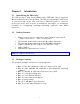
3.1 Wireless Client Bridge-to-Central Wireless Bridge Figure 3-2 Refer t o Figure 3- 2 for t he following set up. N ot e : The EKI - 6311G AP m ode is t he Cent ral Wireless Bridge and EKI - 6311G CB is t he Wireless Client Bridge St e p 1 Set t he EKI - 6311G AP m ode t o perform a bridge ( e x a m ple : I P a ddr e ss: 1 9 2 .1 6 8 .1 .1 ) .
Chapter 4. 4.1 4 .1 .1 All function on Device SYSTEM Adm in ist r a t or Adm in ist r a t or Se t t in gs Use t his m enu t o rest rict m anagem ent access based on a specific password. The default password com es wit h t he inst allat ion guide. Please change t his password as soon as possible, and st ore it in a safe place. Passwords can cont ain from 3- 12 alphanum eric charact ers, and are case sensit ive.
4 .1 .2 Fir m w a r e Figur e 4 - 2 Fir m w a r e Upda t e – TFTP/ FTP You can use TFTP t o upgrade t he firm ware. The " firm ware inform at ion" displays current firm ware version and firm ware dat e. On t he m anaged com put er, run t he TFTP Server ut ilit y. And specify t he folder in which t he firm ware file resides. Aft er running t he TFTP server, ent er t he TFTP server I P and t he filenam e. Click APPLY t o com plet e your change.
4 .1 .3 Con figur a t ion Tools Figur e 4 - 3 Re st or e Fa ct or y D e fa u lt s - Reset t he CPE's configurat ion set t ings t o t he fact ory default values. Check t he " Rest ore Fact ory Default Configurat ion" radio but t on t hen click on APPLY but t on. Ba ck u p se t t in gs/ Re st or e se t t in gs - Check t he " Backup set t ings/ Rest ore set t ings" radio but t on t hen click on APPLY but t on.
4 .1 .4 St a t u s Figur e 4 - 4 You can use t he St at us screen t o see t he connect ion st at us for t he LAN and Wireless LAN int erfaces. I t also displays syst em up t im e and firm ware version. The following it em s are included in t his screen: SYSTEM I N FORM ATI ON - Displays MAC address, Syst em t im e, Current firm ware version and operat ion m ode. LAN I N FORM ATI ON - Displays I P set t ings of LAN port , including I P Address and Subnet Mask.
4 .1 .5 Log Figur e 4 - 5 The Access Point aut om at ically logs ( records) event s of possible int erest in it s int ernal m em ory. I f t here is not enough int ernal m em ory for all event s, logs of older event s are delet ed, but logs of t he lat est event s are ret ained. The Logs opt ion allows you t o view t he Access Point logs.
4 .1 .6 Syst e m Tim e Figur e 4 - 6 The Tim e Configurat ion opt ion allows you t o configure, updat e, and m aint ain t he correct t im e on CPE's int ernal syst em clock. From t his sect ion you can set t he t im e zone t hat you are in and set t he Tim e Server. Tim e Con figur a t ion- Set t he Dat e and Tim e Manually. I f you do not have t he NTP Server opt ion in effect , you can eit her m anually set t he t im e for your Access Point here.
4 .1 .7 Re boot Figur e 4 - 7 Reset Wireless CPE. I n t he event t hat t he Wireless CPE st ops responding correct ly or in som e way st ops funct ioning, you can perform a reboot . Your exist ing set t ings will not be changed. To perform t he reset , click on t he Re boot but t on. You will be asked t o confirm your decision.
4.2 NETWORK 4 .2 .1 N e t w or k 4 .2 .1 .1 Ope r a t in g M ode - Acce ss Poin t I P Assign m e n t D H CP Choose " DHCP ( Dynam ic) " if your rout er support s DHCP and you want t he rout er t o assign an I P address t o t he AP. I n t his case, you do not need t o fill in t he following fields. Figur e 4 - 8 Manual Choose " Manual" if your rout er does not support DHCP or if for any ot her reason you need t o assign a fixed address t o t he AP.
Su bn e t M a sk The subnet m ask of t he local area net work. Ga t e w a y The I P address of t he rout er on t he local area net work. D N S Se r ve r DNS (Dom ain Nam e Syst em ), Penet rat es t he DNS syst em , We m ay look up it s I P by m achine dom ain nam e, Also m ay inst ead look up it s dom ain nam e by m achine I P This ent ry is opt ional. Ent er a DNS Server for t he local net work.
PPPoE Choose " PPPoE" if your I nt ernet support PPPoE Server .You need keyin Use r n a m e and Pa ssw or d t o login PPPoE Server. Figur e 4 - 1 0 4 .2 .1 .2 Ope r a t in g M ode - Acce ss Poin t 4 .2 .1 .3 Ope r a t in g M ode - CB+ AP 4 .2 .1 .4 Ope r a t in g M ode - AP Rou t e r 4 .2 .1 .5 Ope r a t in g M ode - Acce ss Poin t 4 .2 .1 .6 Ope r a t in g M ode - CB+ AP Rou t e r 4 .2 .1 .
4 .2 .2 H ot Spot (Ca pt ive Por t a l) H ot Spot : Enable/ Disable capt ive port al funct ion. Not e, t he CPE will becom e rout er m ode and ALL ssid in Access Point role aft er Hot Spot enabled. D om a in : Set dom ain nam e for hot spot . Pr im a r y Ra diu s: Set prim ary radius server for hot spot user aut hent icat ion. Se con da r y Ra diu s: Set backup radius server for hot spot user aut hent icat ion. N AS I D : Set CPE's NAS I D in RADI US fram es.
4.
4 .3 .1 W i- Fi 1 W ir e le ss Se t t in gs Ra dio St a t u s: Enable/ Disable SSI D. W ir e le ss Role : This SSI D will act as St at ion or Access Point . Not e: only first SSI D can act as st at ion. Ra dio M ode : Set 11g, 11b or 11b+ g m ode. Ra dio Ch a n n e l: Select radio channel or use aut o. Pe e r N ode D ist a n ce : Set dist ance bet ween t his CPE and it 's adj acent . SSI D : Set ( ext ended) service set I D, a.k.a. net work nam e.
4.4 ACL You can set t he access cont rol relat ed set t ing here Figur e 4 - 1 3 4 .4 .1 ACL for W i- Fi 1 W ir e le ss M AC ACL W ir e le ss M AC ACL St a t u s: Enable/ Disable ACL by MAC address. Add N e w M AC Addr e ss: Add a new MAC address t o MAC t able and in act ive st at us. M AC Ta ble : Act ive, t his MAC will be checked. I nact ive, t his MAC will ignore for checking. 4 .4 .2 ACL for W i- Fi 2 4 .4 .3 ACL for W i- Fi 3 4 .4 .
4.5 SNMP You can set t he SNMP Com m unit y and SNMP Trap set t ing here 4 .5 .1 Age n t Se t t in gs SNMP Agent provides a sim ple prot ect ion. Access t o t he SNMP device is cont rolled t hrough com m unit y nam es. The com m unit y nam e can be t hought of as a password. I f you don't have t he correct com m unit y nam e, you can't ret rieve any dat a ( get ) or m ake any change ( set ) . Mult iple SNMP m anagers m ay be organized in a specified com m unit y.
Chapter 5. Specifications The EKI - 6311G Out door Wireless Mult i- Client Bridge/ Access Point operat es seam lessly in t he 2.4 GHz frequency support ing t he I EEE 802.11b/ 802.11g wireless st andards. I t 's t he best way t o add wireless capabilit y t o your exist ing wired net work, or t o add bandwidt h t o your exist ing wireless inst allat ion.
Features High Speed Dat a Rat e Up t o 54Mbps Out put Power up t o 17dBm ± 2dBm I EEE 802.11b/ g Com pliant Access Point / CB+ AP / AP Rout er / CB+ AP Rout er / Hot Spot AP / VLAN AP / VLAN CB+ AP WEP/ WPA/ WPA2/ I EEE 802.1x Aut hent icat or support Dust t ight and Wat ert ight and Weat herproof ( I P67) Wide t em perat ure range and robust m echanical design Power- over- Et hernet ( I EEE802.3af Com pliant ) Technical Specifications D a t a Ra t e s 1, 2, 5.
RF Con n e ct or SMA Type N e t w or k in g Topology Ad- Hoc, I nfrast ruct ure Ope r a t ion M ode Access Point / CB+ AP / AP Rout er / CB+ AP Rout er / Hot Spot AP / VLAN AP / VLAN CB+ AP I n t e r fa ce One 10/ 100Mbps RJ- 45 LAN Port , RS- 232 Console Se cu r it y I EEE802.
Chapter 6. 6.1 Default Settings SYSTEM 6 .1 .1 Adm in ist r a t or Pa r a m e t e r D e scr ipt ion H ost n a m e D e fa u lt Va lu e Advant ech.lan Cu r r e n t Pa ssw or d Pa ssw or d Re - t ype Pa ssw or d 30 I dle Tim e Out En a ble 0.0.0.0 I P a ddr e ss 6 .1 .2 Fir m w a r e Pa r a m e t e r D e scr ipt ion D e fa u lt Va lu e Usin g TFTP Usin g FTP Usin g W EB 6 .1 .
6 .1 .5 Log 6 .1 .6 Syst e m Tim e Pa r a m e t e r D e scr ipt ion D e fa u lt Va lu e Se t t in g by Synchronize wit h an I nt ernet Tim e Server Ye a r / M on t h / D a y 07/ 8/ 20 H ou r : M in u t e : Se con d 02: 26: 06 H ou r s fr om UTC +8 Se r ve r I P pool.nt p.org N TP Se r ve r for Re fe r e n ce pool.nt p.org or 129.132.2.21 Tim e Upda t e for Eve r y 0/ 0/ 0 6 .1 .
6.2 NETWORK 6 .2 .1 N e t w or k Pa r a m e t e r D e scr ipt ion D e fa u lt Va lu e Ope r a t in g Access Point I P Assign m e n t Manual I P Addr e ss 192.168.1.1 Su bn e t M a sk 255.255.255.0 Ga t e w a y 0.0.0.0 D N S Se r ve r 0.0.0.0 Lin k I n t e gr it y Disable PPPoE Use r n a m e PPPoE Pa ssw or d 6 .2 .2 H ot spot Pa r a m e t e r D e scr ipt ion H ot Spot St a t u s D e fa u lt Va lu e Disable D om a in Pr im a r y Ra diu s 0.0.0.0 1812 Se con da r y Ra diu s 0.
6.3 WIRELESS 6 .3 .1 W i- Fi 1 Pa r a m e t e r D e scr ipt ion D e fa u lt Va lu e Country TAI WAN Radio Status Enable Wireless Role Access Point Radio Mode 802.11b+ g Radio Channel Channel 1, 2412MHz Antenna mode I nt ernal Peer Node Distance 100 m et ers SSID Advant ech/ 1 Transmission Power 17dBm Frag.
6 .3 .2 W i- Fi 2 Pa r a m e t e r D e scr ipt ion D e fa u lt Va lu e Country TAI WAN Radio Status Disable Wireless Role Access Point Radio Mode 802.11b+ g Radio Channel Channel 1, 2412MHz Peer Node Distance 100 m et ers SSID Advant ech/ 2 Transmission Power 17dBm Frag.
6 .3 .3 W i- Fi 3 Pa r a m e t e r D e scr ipt ion D e fa u lt Va lu e Country TAI WAN Radio Status Disable Wireless Role Access Point Radio Mode 802.11b+ g Radio Channel Channel 1, 2412MHz Peer Node Distance 100 m et ers SSID Advant ech/ 3 Transmission Power 17dBm Frag.
6 .3 .4 W i- Fi 4 Pa r a m e t e r D e scr ipt ion D e fa u lt Va lu e Country TAI WAN Radio Status Disable Wireless Role Access Point Radio Mode 802.11b+ g Radio Channel Channel 1, 2412MHz Peer Node Distance 100 m et ers SSID Advant ech/ 4 Transmission Power 17dBm Frag.
6.4 ACL 6 .4 .1 ACL for W i- Fi Pa r a m e t e r D e scr ipt ion D e fa u lt Va lu e W ir e le ss M AC ACL St a t u s Disable Add N e w M AC Addr e ss 00: 00: 00: 00: 00: 00 W ir e le ss On / Off Sch e du lin g St a t u s Disabled Sch e du lin g on Su n da y 0 24 Sch e du lin g on M on da y 0 24 Sch e du lin g on Tu e sda y 0 24 Sch e du lin g on W e dn e sda y 0 24 Sch e du lin g on Th u r sda y 0 24 Sch e du lin g on Fr ida y 0 24 Sch e du lin g on Sa t u r da y 0 24 6 .
6 .4 .3 ACL for W i- Fi 3 Pa r a m e t e r D e scr ipt ion D e fa u lt Va lu e W ir e le ss M AC ACL St a t u s Disable Add N e w M AC Addr e ss 00: 00: 00: 00: 00: 00 W ir e le ss On / Off Sch e du lin g St a t u s Disabled Sch e du lin g on Su n da y 0 24 Sch e du lin g on M on da y 0 24 Sch e du lin g on Tu e sda y 0 24 Sch e du lin g on W e dn e sda y 0 24 Sch e du lin g on Th u r sda y 0 24 Sch e du lin g on Fr ida y 0 24 Sch e du lin g on Sa t u r da y 0 24 6 .4 .
6.5 SNMP Pa r a m e t e r D e scr ipt ion D e fa u lt Va lu e Age n t St a t u s Enable Syst e m Loca t ion Syst e m Con t a ct Syst e m N a m e Advant ech Syst e m D e scr ipt ion Advant ech Wireless AP/ CB Re a d On ly Com m u n it y public Re a d W r it e Com m u n it y Privat e 6.
Chapter 7. Regulatory Compliance Information Federal Communication Commission Interference Statement This equipment has been tested and found to comply with the limits for a Class B digital device, pursuant to Part 15 of the FCC Rules. These limits are designed to provide reasonable protection against harmful interference in a residential installation.
Antenna type Antenna Gain Patch 9dBi Omni 5dBi 51