
User's Manual

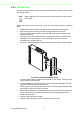


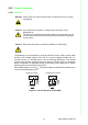

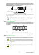


Table Of Contents
- 1 Introduction
- 2 Getting Started
- 3 Utility Configuration
- 4 Web Interface
- 4.1 Overview
- 4.2 Accessing the Web Page
- 4.3 Overview
- 4.4 Network Settings
- 4.5 Wireless Settings
- 4.6 Alarm
- 4.7 Administration
- 5 Telnet/Serial Console Configuration

EKI-6233BN User Manual 17
There are two power inputs for normal and redundant power configurations. The
power input 2 is used for wiring a redundant power configuration. See the following
for terminal block connector views.
Figure 2.16 Terminal Receptor: Power Input Contacts
To wire the power inputs:
Make sure the power is not connected to the gateway or the power converter before
proceeding.
1. Loosen the screws securing terminal block to the terminal block receptor.
2. Remove the terminal block from the gateway.
Figure 2.17 Removing a Terminal Block
3. Insert a small flat-bladed screwdriver in the V1+/V1- wire-clamp screws, and
loosen the screws.
4. Insert the negative/positive DC wires into the V+/V- terminals of PW1. If setting
up power redundancy, connect PW2 in the same manner.
5. Tighten the wire-clamp screws to secure the DC wires in place.
Figure 2.18 Installing DC Wires in a Terminal Block
6. Align the terminal block over the terminal block receptor on the gateway.
7. Insert the terminal block and press it in until it is flush with the terminal block
receptor.
P-Fail
V2- V2+ V1- V1+
PWR2 PWR1
Loosening
Wire-clamp
Screws
Installing
DC Wires
Securing
Wire-clamp
Screws