Industrial PCs applied in / Logistics und Warehouse / Heavy Duty / Fleet Management / Stationary and Automation DLoG Config Manual 3.
This manual contains a detailed description of the product and we have made every effort to make it as accurate as possible. However, this is not a guarantee of the features or the functionality of the product. We reserve the right to modify the contents of this document at any time and without prior notice.
Table of Contents 1. About this manual .............................................................................. 1 1.1. Software version described ............................................................................. 1 1.2. Retain this manual ........................................................................................... 1 1.3. For qualified personnel .................................................................................... 1 1.4. Design method...........................
8. Automatic Switch-off........................................................................ 16 8.1. Configuration dialog on DLoG MPC, IPC, ITC .............................................. 16 8.1.1. 8.1.2. 8.1.3. 8.1.4. 8.1.5. Switch-On............................................................................................... 19 Switch-Off............................................................................................... 20 Special features of the switch-on/-off options ..............
14. 13.3. Basic legend for signal strength ................................................................. 39 13.4. WLAN status window settings dialog ......................................................... 40 13.5. WLAN status window and radio cards ....................................................... 43 13.6. Write WLAN log file .................................................................................... 43 Software Activation .......................................................
List of Figures Figure 4.1: DLoG Config main menu with operating system WES 7.................................. 5 Figure 5.1: DLoG Config Information: FBWF is activated ................................................ 10 Figure 6.1: DLoG MTC 6 Hardware monitor Menu .......................................................... 11 Figure 7.1: DLoG MPC, IPC and ITC Environment menu ................................................ 12 Figure 7.2: DLoG MTC 6 Environment menu .........................................
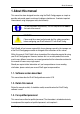
About this manual 1. About this manual This manual has been designed to make using the DLoG Config program as simple as possible and provide expert assistance if problems should occur. It contains important information on using the program safely and efficiently. To find information fast and easily, use the comprehensive Index at the back of the manual! WARNING Please read this manual and take note of all the safety precautions before configuring your DLoG Industrial PC with DLoG Config.
About this manual 1.4. Design method 1.4.1. Risk of injury or death This symbol indicates hazards that pose a risk to life and limb (such as contacting the power supply): The following levels apply, denoted by the keywords DANGER, WARNING, and CAUTION: DANGER There is an immediate risk of death / serious injury. WARNING There is a possible risk of death / serious injury. CAUTION Mild injury is possible. 1.4.2.
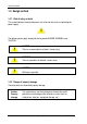
About this manual 1.4.3. Hints This symbol indicates hints that help you to understand how to use the product or the manual. 1.4.4. Additional design elements Lists are indicated with bullet points, for example: • DLoG MPC • DLoG MTC Instructions are numbered, for example: 1. Insert a CD. 2. Press . Key display Key names are shown in angle brackets: , , , , etc. Menu options, commands, dialog fields Examples: In the Edit menu you will find the command Paste | Values.
Basic safety guidelines 2. Basic safety guidelines Caution: Property damage DLoG Config contains important settings for your DLoG Industrial PC. Incorrect settings, such as those in the Automatic Switch-off menu, can disable the functions of your computer. Only qualified technical personnel, e.g. persons qualified in computer/network/system administration may perform DLoG Config settings.
Overview of functions 4. Overview of functions The DLoG Config software can be used to configure the DLoG Industrial PCs listed in section 3 Area of applicability . The DLoG Config software automatically recognizes the Industrial PC type and the installed operating system. The configuration dialog differentiates the various systems and is displayed according to the device.
Overview of functions 6 Menu Function Hardware Monitor Information display: e.g. serial number of the device and current operating temperature Environment Information display: Statistics and data on the environment controller, such as 'hard' switch-offs Automatic Switch-off Configures the automatic switch-off behaviour (delay time, ignition, etc.) Front Panel Defines the assignment of DLoG Industrial PCs optional front panel keys System Settings Configures Windows logon, taskbar display etc.
Installation 5. Installation 5.1. System requirements The following operating systems are supported: • MSWindows 2000, Service Pack 4 • MS Windows XP • MS Windows XP Embedded • MS Windows 7 • MS Windows Embedded Standard 7 (WES 7) 5.2. Pre-installed on DLoG computers In most cases DLoG Config is pre-installed on each DLoG Industrial PC by the DLoG production department. 5.3. Subsequent installation An installation program is available for subsequent installation. Start the dlog config.
Installation 5.5. Files The following important files are located in the DLoG Config installation directory: DLoGCfg.exe Main program for configuration Config_Local.cfg Configuration file with DLoG Config settings – all local settings that are not saved directly in the hardware are saved here. More information: Read section 13.6 Write WLAN log file. DLOGKEYBOARD.EXE Software keyboard main program KEYBOARD.CFG The layout and functionality of the software keyboard are set here.
Installation Command line parameters The parameter MAKETEXT is available to translate software into foreign languages. This means text resources can be exported to *.txt files. Each time a file is created, a message appears prompting the user to confirm it. Simply add the language code to the end of this newly generated text file. For example, DLoGCfg_.txt would then be DLoGCfg_ENG.txt if it contained the English text. During text file generation, files with the same name are automatically overwritten.
Installation 5.6.7. FBWF advice at the start of the program If the hard drive on which the config files are saved is enabled for FBWF, the following message appears at the DLoG Config start-up: Figure 5.1: DLoG Config Information: FBWF is activated De-activate the FBWF Filter, if necessary. 10 Manual V3.
Hardware Monitor 6. Hardware Monitor In the Hardware Monitor menu, Industrial PC system information is displayed: • DLoG serial number • Industrial PC model • Installed processor • Firmware version • BIOS version • Inside temperature of the Industrial PC Example DLoG MTC 6: Figure 6.1: DLoG MTC 6 Hardware monitor Menu DLoG Config Manual V3.
Environment 7. Environment The environment controller in the DLoG Industrial PC features monitoring and statistics functions. The Environment menu provides information on the measured values. 7.1. Information on DLoG MPC, IPC, ITC Figure 7.1: DLoG MPC, IPC and ITC Environment menu 12 Manual V3.
Environment Environment Total running time of device Total time the device was on Backlight running time Total time that backlighting was on Power key switch-on count Shows how often the computer was switched on with the power key Ignition switch-on count Shows how often the computer was switched on via the vehicle ignition Power key switch-off count Shows how often the computer was switched off with the power key Automatic switch-off count Shows how often the computer was switched off via the i
Environment 7.2. Information on DLoG MTC 6 Figure 7.2: DLoG MTC 6 Environment menu Total uptime terminal Total time the device was on Operating time display backlight Total time that backlighting was on Counter power on Shows how often the computer was switched on with the power key Counter booting activities Shows how often the computer was switched on via the vehicle ignition Counter shut down events Shows how often the computer was switched off via the ignition 14 Manual V3.
Environment Counter hard power off events Shows how often the computer was turned off using 'hard' switch-off Operation outside certified temperature Shows how often the computer switched off due to excess temperature Error temp sensor Shows how often temperature sensor errors occurred. If this error message occurs frequently, please send your unit in to be serviced. DLoG Config Manual V3.
Automatic Switch-off 8. Automatic Switch-off In the Automatic Switch-off menu, the behaviour of computer switch-on and switch-off is defined. 8.1. Configuration dialog on DLoG MPC, IPC, ITC The top left of the menu shows whether the option Automatic Switch-off is available and activated. The option can be activated in the Software Activation menu (after purchasing the option). Figure 8.1: Automatic Switch-off menu on DLoG MPC, IPC, ITC Don’t forget to save these settings with the Save button.
Automatic Switch-off Settings After-run time and Timeout to terminate programs on shutdown If you do not want the computer to shut down immediately after switching it off using the ignition or power key, but rather it should remain on for a time, then enter an after-run time (in seconds) here. Shutdown times The length of time until shutdown consists of two counters: 1. After-run time The after-run time begins with the switching off of the ignition.
Automatic Switch-off Show taskbar icon Selecting this options creates a symbol for DLoG Config in the taskbar. The symbol indicates the power status as follows: Green: Power status is OK; ignition is on. Flashing yellow and red: The ignition has been switched off and the after-run time is counting down. Red: The computer is in shutdown or switch-off mode. Unable to read power status. Double-click or right-click with the mouse to open a popup menu where DLoG Config can be started.
Automatic Switch-off 8.1.1. Switch-On with ignition Caution: Property damage with ignition and power key Caution: Property damage Only for DC devices: The computer switches on automatically when the ignition is started. It cannot be switched on with the power key. Switch-on with ignition is only allowed with DC devices; this blocks AC devices and they cannot be restarted. Only for DC devices: The computer can be switched on with the power key if the ignition is on.
Automatic Switch-off 8.1.2. Switch-Off with ignition Only for DC devices with automatic switch-off: Automatic switch-off is activated when the ignition is switched off. with ignition and power key Only for DC devices with automatic switch-off: Automatic switch-off is activated when the ignition is switched off. The power key shortens the defined after-run time and initiates computer shutdown.
Automatic Switch-off 8.1.3. Special features of the switch-on/-off options On DLoG MPC, IPC and ITC the following message is displayed upon activating a switch-on option with ignition: Figure 8.2: Automatic switch-on message for DC/AC devices This information appears for safety's sake each time a switch-on with ignition option is activated. Caution: Property damage Switch-on with ignition is only allowed with DC devices; this blocks AC devices and they cannot be restarted. 8.1.4.
Automatic Switch-off 8.2. Configuration dialog on DLoG MTC 6 Caution: Property damage Each DLoG MTC 6 has been equipped with an automatic shutdown function. This function has been pre-configured for vehicle use already and governs the power-up and shutdown procedures for the DLoG MTC 6 connected to a car ignition. The automatic shutdown settings for DLoG MTC 6 devices that are not going to be installed into a vehicle must also be correctly set for the device type! Figure 8.
Automatic Switch-off Settings The settings on the DLoG MTC 6 correspond to the MPC/IPC/ITC settings in section 8.1 Configuration dialog on DLoG MPC, IPC, ITC. Switch on with ignition with ignition and power key The Industrial PC switches on automatically when the ignition is started. It cannot be switched on with the power key. The Industrial PC can be switched on with the power key if the ignition is on. It cannot be switched on with the power key alone.
Automatic Switch-off Shutdown to hibernation mode 24 If the Industrial PC is switched off using the ignition or the power key, it goes into hibernation mode. When this happens, a copy of the main memory is written to a file, accelerating the startup of the computer. This option must be activated in the power management centre of the computer (Power Properties). Manual V3.
Front Panel 9. Front Panel In the Front Panel menu, the keys (also called soft keys) located on the DLoG Industrial PC front panel can be programmed. This does not apply to the keys Power on/off, +/- Brightness and Backlight on/off! All keys depicted in grey/white can have two assignments. Use to switch between the assignments. Character strings cannot be assigned to single keys. Only one character per key is possible. The keys , and may be used in combination, e.g.
Front Panel 9.2. Configuration dialog on DLoG MTC 6 Figure 9.2: DLoG MTC 6 Front Panel Keyboard menu 26 Manual V3.
Front Panel 9.3. Assigning front panel keys Identical for all DLoG Industrial PCs! 1. Select the key to be changed, it appears in the Current assignment field. 2. Press the Change key button. The Define key input dialog appears. 3. Press the desired key assignment. The selected key assignment appears in the New assignment field. 4. Save these settings with the Save button. If an assignment is given twice to the same key, a corresponding warning message appears. 9.4.
Common System Settings 10. Common System Settings In the Common System Settings menu, parts of the Windows System can be configured. The content of this menu differs depending on the operating system. 10.1. Windows 2000, XP, XP Embedded Figure 10.1: Common System Settings MS Windows 2000, XP, XP Embedded 10.1.6. Automatic Windows Logon Logon automatically as Enable or disable the Automatic Windows Logon. Domain name User name Password Logon data for the Automatic Windows Logon must be entered.
Common System Settings 10.1.7. Logon with software keyboard Show software keyboard at logon If this check box is selected, the software keyboard is already available to the user upon logging in. Keyboard definition for the logon A CFG file and hence a particular keyboard layout can be specified for the logon (it may differ from the default keyboard). Changes to this setting are activated only after the computer has been restarted.
Common System Settings Remote Desktop logon with SW-Keyboard Activate support for Remote Desktop After a remote access to the current computer, the software keyboard can be activated for logging back in. Keyboard definition for logon The CFG file for the software keyboard is specified, e.g. "C:\DLoG\Keyboard.cfg" Keyboard / front key locking Lock keyboard and front keys Using this setting , all keyboard inputs/key inputs on the DLoG industrial computer can be locked.
Common System Settings 10.2. Windows 7 and WES 7 10.2.8. Automatic Windows Logon Logon automatically as Enable or disable the Automatic Windows Logon. Domain name User name Password Logon data for the Automatic Windows Logon must be entered. 10.2.9.
Common System Settings 10.2.10. 32 Software keyboard Show software keyboard at logon If this check box is selected, the software keyboard is already available to the user upon logging in. Keyboard definition for the logon A CFG file and hence a particular keyboard layout can be specified for the logon (it may differ from the default keyboard). Changes to this setting are activated only after the computer has been restarted.
Common System Settings 10.2.11. Keyboard / front key locking Lock keyboard and front keys Using this setting , all keyboard inputs/key inputs on the DLoG industrial computer can be locked. - Front panel buttons - External keyboard - Software keyboard (via touch screen) Locking is only active after restarting the computer. Password for key lock (numeric only) Locking is only activated if a max. 20 character long keyword is defined. For this only numbers are used.
Network Settings 11. Network Settings This configuration dialog is identical for all DLoG Industrial PCs. 11.1. Common In the Common menu under Network Settings, you can make settings for the network adapter (LAN and WLAN). Find information about settings for the network adapter currently selected in the Current settings window. The System Settings button opens the Windows dialog for networks. Figure 11.1: Network Settings | Common menu Computer name The DLoG Industrial PC host name can be changed.
Network Settings Network adapter Selection list Select the Network adapter Obtain address automatically (DHCP) With this setting, the network configuration is obtained from a DHCP server. Use the following IP address Here the IP address, subnet mask and default gateway can be entered manually. Use the following DNS server addresses Here the DNS servers to be used can be entered manually. 11.2.
Network Startup 12. Network Startup You can define programs in this menu which should be started after a network connection is successfully established with a server (after every boot of the operating system). This configuration dialog is identical for the DLoG MPC, IPC, ITC and MTC. Figure 12.1: Network Startup Autostart programs Multiple programs can be specified. The programs are started in the order given. The settings are activated only after the computer is restarted.
Network Startup IP address for startup check Automatic selection (DNS or WINS server) of network adapter The desired network adapter can be specified here. Possible selections are: - All adapters - COM2 VPN adapter - IntelR PRO / 100VE Network Connection Include default gateway in check If this checkbox is checked, then the default gateway is also included when searching for an IP address.
WLAN 13. WLAN In this menu, you can configure whether a WLAN status window will be displayed on the DLoG Industrial PC, with information about signal strength and quality of the WLAN connection. This configuration dialog is identical for the DLoG MPC, IPC, ITC and MTC. 13.1. Information on the WLAN status window Example of a WLAN status window Figure 13.
WLAN 13.2. Signal strength and quality S = Signal strength This value provides information about the strength of the signal received by the DLoG computer. The signal strength can be displayed as a dBm value, in percentages, or as a diagram, depending on the configuration selected in the WLAN dialog. Q = Quality This value provides information about the quality of the signal received by the DLoG computer.
WLAN 13.4. WLAN status window settings dialog Figure 13.2: WLAN Status Window dialog type Window settings Dialog type In the selection list, select the desired design for the WLAN status window. The signal strength and quality can be displayed as dBm values, percentages, or a bar chart. Auto adjust Dialog width to host/IP info The width of the WLAN status window can be defined as a fixed value. Otherwise, it depends on the length of the host name and the IP address.
WLAN Display SSID SSID (Service Set Identifier) is displayed in the WLAN Status Window. Windows is always on top The WLAN status window will always be displayed on top of other windows. Show title bar Display the WLAN status window with a title bar. Show in task bar The WLAN status window will appear in the task bar. Window can be activated / moved The position on the WLAN status window on the screen can be moved. If the title bar is displayed, the window can be activated.
WLAN Connect program Start program on each new connect or start after ... This setting is used to start any arbitrary software program. The program may optionally be started: • after every entry into the WLAN area • or periodically; if necessary, enter the time interval. If a WLAN connection exists, the program is started at the specified intervals.
WLAN 13.5. WLAN status window and radio cards The WLAN status window works exclusively with radio cards which support WMI. The WMI class is configured in "config_local.cfg" in the line "Noiseselect_01". The WMI selection string in the format: NoiseSelect_XX=Card-Name,SELECT * .... For XX, substitute a number from 01 to 20; at most 20 different WLAN cards can be supported . For the card name, a few characters at the start of the WLAN adapter name are enough (not case sensitive).
WLAN Figure 13.3: Example of a WLAN log file Information in the WLAN log file: The following basically applies: • Only the information which is displayed in the WLAN status window is written in the WLAN log file (according to the definition in the DLoG Config menu WLAN Status Window). • The maximum size of the WLAN log file is 50 MB. When this size is reached, the DLoG Config automatically creates BAK files, which are sequentially numbered.
Software Activation 14. Software Activation In the Software activation menu, options such as automatic switch-off and software keyboard can be activated. If these options are purchased at a later date (after the DLoG Industrial PC delivery), customers receive an activation key or a license file, which must be entered here. The automatic switch-off function in the DLoG MTC 6 is always available and does not need to be activated. Figure 14.1: Software Activation menu DLoG Config Manual V3.
Software Activation 14.1. Activate automatic switch-off Activate the automatic switch-off as follows: 1. Activate the Product code in the line AOFF Automatic switch-off. 2. Enter the activation key you received with the purchase of the option. Or: Click Search file under Import license file and load the license file that contains this key. 3. Save the settings. 14.2. Activate software keyboard Activate the software keyboard as follows: 1. Activate the Product code in the line SWKB Software keyboard. 2.
Enhanced Write Filter 15. Enhanced Write Filter The Enhanced Write Filter menu is only relevant for the embedded operating systems (XP Embedded and WES 7)! The Enhanced Write Filter menu is only relevant for the Microsoft Windows XP Embedded operating system! If EWF is not installed, no changes can be performed. This configuration dialog is identical for the DLoG MPC, IPC, ITC and MTC. Write protection is enabled and managed in the Enhanced Write Filter menu.
Enhanced Write Filter The computer's EWF drives are displayed in the EWF Drives field (there is usually only one). The settings below apply to the EWF drive selected here. Set boot command (BootCmd) No command The set boot commands are deactivated again. Activate write protection (ENABLE) Activates write protection: All system changes are written exclusively to the main memory; they are discarded when the computer is restarted.
File Based Write Filter 16. File Based Write Filter The File Based Write Filter menu is only relevant for the embedded operating systems: XP Embedded and WES 7. 16.1. FBWF menus: Current and target status of the installation The left column of the FBWS menu always shows the currently installed FBWF configuration; the right column shows the newly defined configuration after the computer is restarted. Current Status Settings Target Status Figure 16.
File Based Write Filter 16.2. FBWF Configuration The File Based Write Filter (FBWF) offers the possibility to protect a partition from changes. In contrast to the Enhanced Write Filter (EWF), the FBWF filters on a file basis and offers many additional options for configuration. The cache for intermediate storage of the changes can be set for between 64 and 1024 MB. Current Configuration The currently valid FBWF settings are displayed.
File Based Write Filter 16.2.12. Exceptions for write protection Here you can define exceptions for write protection. Entire directories or individual files can be specified. Changes to files on the exception list are written directly to the file system, as usual. The left column of the menu shows the currently set FBWF configuration; the right column shows the newly defined configuration after the computer is restarted. Figure 16.
File Based Write Filter Exceptions after restart Add/remove After clicking on Add or Remove, a list of hard drives and files is displayed. • When the desired configuration is complete: Don't forget to save the settings. 16.2.13. Modified files in the cache When FBWF is active, files are shown here that are protected by FBWF and that were changed during the run time.
File Based Write Filter Procedure: • Select the individual lines in the list. • Press the Write changes to the disk button if the changed data that is still in the cache is to be written to the respective hard drive. • Or select Delete file from cache and restore original if the modified file in the cache should be deleted. Error messages FBWF Error (1) Figure 16.4: FBWF error: File is in the FBWF cache Explanation: DLoG Config Files could not be written to the files, as they did not physically exist.
File Based Write Filter FBWF Error (53) Figure 16.5: FBWF error: For files that are currently being accessed Explanation: 54 Files which are currently being accessed cannot be written to data media. With OK the file is skipped, the procedure Write changes to data media is carried out for the next file on the list. With Cancel, the procedure Write changes to data media is interrupted. Manual V3.
Settings 17. Settings In this menu, DLoG Config is configured with respect to password, language etc. This configuration dialog is identical for the DLoG MPC, IPC, ITC and MTC. Figure 17.1: Settings menu Password protection Use password protection for DLoG Config DLoG Config A password can be activated to allow access to programs. Enter a password and repeat the entry in the Repeat password field. This is case-sensitive. Manual V3.
Settings Allow read access without password: Reading all data DLoG Config can be started without a password. It is possible to read all data, but no changes may be made to the settings. Limited to data A password is not required to start DLoG Config. Reading of without COM port data is limited: The Environment, Automatic Switch-off and access Front Panel menus are not available. Language Language setting The language of the DLoG Config menus is defined.
Settings Caution: Property damage During import not all data is checked for validity; rather the data is saved in the way that it is defined in the import file. False information could lead to failure of DLoG Industrial PC (such as malfunctions, data loss, equipment damage etc.).
Settings 17.1. Command lines parameter IMPORT (only for administrators) The parameter IMPORT is available for import using batch job (DLoG Config V 2.3 and higher). Example: DLoGCfg IMPORT=AnyExportedData.cfg The CFG file to be imported must be generated using export from DLoG Config. The CFG filename must contain the entire path (or at least ".\" for the current directory).
Settings 17.2. Info header of an export file The info header of an export file contains the following information: ;-----------------------------------------------------; DLoG Config export file ; ; Exported from computer: MPC5XPEMBSP2 ; Hardware serial-number: 205004056587 ; Export timestamp (YMD): 2005/06/18 20:30:13 ;------------------------------------------------------ [General] DLoGCfgExportVer=1 DLoGCfgExportSNR=205004056587 DLoG Config Manual V3.
Index 52BInfo header of an export file Index AC – DC configurations .................................. 56 AC devices ............................................... 19, 21 Access point ................................................... 44 Activate automatic switch-off .......................... 46 Activate software keyboard ............................ 46 Activation........................................................ 16 Activation key .................................................
52BInfo header of an export file Index Front-panel button with program call.............. 27 Fullscreen mode ............................................ 18 Hard switch-off ............................................... 13 Hardware monitor .......................................... 11 Hibernation .................................................... 24 Hibernation mode........................................... 20 Hotkey............................................................ 41 Ignition .............
Index 52BInfo header of an export file Start program using front panel button ........... 27 Starting the program ........................................ 9 STATNET ....................................................... 58 Subnet mask .................................................. 35 Subsequent installation .................................... 7 Switch-off ................................................. 13, 14 Switch-off time................................................ 17 Switch-on ............