
User manual

7 ASMB-310IR/310 User Manual
Chapter 1 Overview
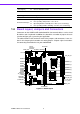
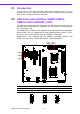
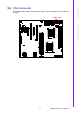
Figure 1.2 Rear I/O
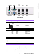
Table 1.2: Onboard LAN LED Color Definition
10/100/1000 Mbps LAN Link/Activity LED Scheme
Left LED Right LED
10 Mbps
Link Off Green
Active Off Blinking green
100 Mbps
Link Amber Green
Active Amber Blinking green
1000 Mbps
Link Green Green
Active Green Blinking green
No Link Off Off
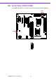
Table 1.3: Jumpers
Label Function
JP_CMOS1 CMOS Clear
JP_BMC1 BMC Enable (2-3) or Disable (1-2)
Table 1.4: Connectors
Label Function
ATX_8P_P0 SSI EPS 12 V auxiliary power connector (for CPU0) and memory
ATX_8P_P1 SSI EPS 12 V auxiliary power connector (for CPU1) and memory
ATX_P24 SSI EPS 24-pin main power connector (for system)
COM2 Serial port: RS-232
CPU0 Intel LGA1366 CPU0 socket
CPU1 Intel LGA1366 CPU1 socket
PS2 Mouse
COM1
LAN1
IPMI
LAN1
LAN2
PS2 Keyboard
VGA USB56
USB12
USB34
Left
Right