ARK-5280 Fanless, PC Board Expandable, Embedded Box Computer User Manual
Copyright The documentation and the software included with this product are copyrighted 2006 by Advantech Co., Ltd. All rights are reserved. Advantech Co., Ltd. reserves the right to make improvements in the products described in this manual at any time without notice. No part of this manual may be reproduced, copied, translated or transmitted in any form or by any means without the prior written permission of Advantech Co., Ltd. Information provided in this manual is intended to be accurate and reliable.
Product Warranty (1 year) Advantech warrants to you, the original purchaser, that each of its products will be free from defects in materials and workmanship for one year from the date of purchase. This warranty does not apply to any products which have been repaired or altered by persons other than repair personnel authorized by Advantech, or which have been subject to misuse, abuse, accident or improper installation.
Declaration of Conformity CE This product has passed the CE test for environmental specifications when shielded cables are used for external wiring. We recommend the use of shielded cables. This kind of cable is available from Advantech. Please contact your local supplier for ordering information. Test conditions for passing included the equipment being operated within an industrial enclosure.
ARK-5280 Series Model There are two sub-models in ARK-5280 series as listed below: ARK-5280-1S3A1 LV Celeron M 1.3 GHz Embedded Box Computer, with VGA, Fast Ethernet, PS/2 (K/B & Mouse), 3 x RS-232, 1 x RS-232/ 422/485, 2 x USB, DVI, Audio ARK-5280-1S6A1 LV Pentium M 1.6GHz, Embedded Box Computer, with VGA, Fast Ethernet, PS/2 (K/B & Mouse), 3 x RS-232, 1 x RS-232/ 422/485, 2 x USB, DVI, Audio Packing List Before setting up the system, check that the items listed below are included and in good condition.
Safety Instructions 1. Read these safety instructions carefully. 2. Keep this User's Manual for later reference. 3. Disconnect this equipment from any AC outlet before cleaning. Use a damp cloth. Do not use liquid or spray detergents for cleaning. 4. For plug-in equipment, the power outlet socket must be located near the equipment and must be easily accessible. 5. Keep this equipment away from humidity. 6. Put this equipment on a reliable surface during installation.
20° C (-4° F) OR ABOVE 60° C (140° F). THIS COULD DAMAGE THE EQUIPMENT. THE EQUIPMENT SHOULD BE IN A CONTROLLED ENVIRONMENT. 16. CAUTION: DANGER OF EXPLOSION IF BATTERY IS INCORRECTLY REPLACED. REPLACE ONLY WITH THE SAME OR EQUIVALENT TYPE RECOMMENDED BY THE MANUFACTURER, DISCARD USED BATTERIES ACCORDING TO THE MANUFACTURER'S INSTRUCTIONS. The sound pressure level at the operator's position according to IEC 7041:1982 is no more than 70 dB (A).
Wichtige Sicherheishinweise 1. Bitte lesen sie Sich diese Hinweise sorgfältig durch. 2. Heben Sie diese Anleitung für den späteren Gebrauch auf. 3. Vor jedem Reinigen ist das Gerät vom Stromnetz zu trennen. Verwenden Sie Keine Flüssig-oder Aerosolreiniger. Am besten dient ein angefeuchtetes Tuch zur Reinigung. 4. Die NetzanschluBsteckdose soll nahe dem Gerät angebracht und leicht zugänglich sein. 5. Das Gerät ist vor Feuchtigkeit zu schützen. 6.
e. Das Gerät ist gefallen und/oder das Gehäuse ist beschädigt. f. Wenn das Gerät deutliche Anzeichen eines Defektes aufweist. 15. VOSICHT: Explisionsgefahr bei unsachgemaben Austausch der Batterie. Ersatz nur durch densellben order einem vom Hersteller empfohlene-mahnlichen Typ. Entsorgung gebrauchter Batterien navh Angaben des Herstellers. 16. ACHTUNG: Es besteht die Explosionsgefahr, falls die Batterie auf nicht fach-männische Weise gewechselt wird.
ARK-5280 User Manual x
Contents Chapter 1 Overview .......................................................... 2 1.1 1.2 1.3 1.4 Chapter Introduction ....................................................................... 2 Features ............................................................................. 2 1.2.1 1.2.2 1.2.3 Fanless Power Computing Performance ........................ 2 Compact, Extremely Robust Construction .................... 2 Highly Optimized Integration ........................................
Figure 2.7:PS/2 Mouse Connector ............................... 15 Table 2.6:PS2 Keyboard and PS2 Mouse Connector .. 15 2.2.10 VGA Connector ........................................................... 16 Figure 2.8:VGA Connector .......................................... 16 Table 2.7:Table 2.10: VGA port pin assignments ...... 16 2.2.11 USB Connector ............................................................ 16 Figure 2.9:USB Connector .......................................... 17 Table 2.
4.4.3 4.4.4 4.4.5 4.4.6 4.4.7 4.4.8 4.4.9 4.4.10 4.4.11 4.4.12 4.4.13 4.4.14 4.5 Advanced Chipset Features............................................. 37 4.5.1 4.5.2 4.5.3 4.5.4 4.5.5 4.5.6 4.5.7 4.5.8 4.5.9 4.5.10 4.5.11 4.5.12 4.5.13 4.5.14 4.5.15 4.5.16 4.5.17 4.5.18 4.6 Quick Power On Self Test ........................................... 35 First/Second/Third/Other Boot Device ........................ 35 Swap Floppy Drive ......................................................
4.6.8 4.6.9 4.6.10 4.6.11 4.6.12 4.6.13 4.6.14 4.6.15 4.6.16 4.6.17 4.6.18 4.6.19 4.7 Power Management Setup............................................... 46 4.7.1 4.7.2 4.7.3 4.7.4 4.7.5 4.7.6 4.7.7 4.7.8 4.7.9 4.7.10 4.7.11 4.7.12 4.7.13 4.7.14 4.7.15 4.7.16 4.7.17 4.8 ACPI function .............................................................. 46 ACPI Suspend Type ..................................................... 46 Power Management .....................................................
4.13 Chapter Chapter 5 PCI SVGA Setup ........................................... 54 5.1 Introduction ..................................................................... 54 5.2 Installation of the SVGA Driver ..................................... 54 5.3 Further information ......................................................... 58 5.1.1 5.1.2 5.1.3 5.2.1 Chipset ......................................................................... 54 Display memory ........................................
ARK-5280 User Manual xvi
CHAPTER 1 2 Overview This chapter gives background information on the ARK-5280, including an overview and specifications.
Chapter 1 Overview 1.1 Introduction ARK-5280 is a powerful, robust and fanless Embedded Box Computer. The high performance ARK-5280 is equipped with socket 479 that supports Intel Celeron-M and Pentium-M processors, which is highly suitable for embedded and industrial PC applications requiring high processor performance within a limited space. Featuring two PCI slots for application expansion and system integration, ARK-5280 also carries four USB 2.0 and four serial port communication I/O interfaces.
1.3 Hardware Specifications 1.3.1 Processor System Processor Support Supports uFCPGA2, 478 pin embedded Intel Pentium M or Celeron M processors, and supports up to Intel Pentium M processor 745 at 1.8 GHz • Celeron M 1.3 GHz (ARK-5280-1S3A1) • Pentium M 1.6 GHz (ARK-3380-1S6A1) System Chipset • Intel 855GME Graphics Memory Controller Hub (GMCH) Chipset • Intel FW82801DB I/O Controller Hub 4 (ICH4) Chipset • 400 MHz FSB BIOS: 4 Mbit Flash BIOS, supports Plug & Play, APM 1.
Ethernet Interface Built-in Dual RJ45 ports as LAN 1 and LAN 2 1.3.4 Audio Audio Interface • Audio controller on the ICH4 chip. • Realtek ACL202 AC97 Codec • AC97 3D surround stereo sound, Dual 2.2 W Amplifier • Supports Line_In, Speaker_Out, and Microphone_In connectors on the front side. 1.3.5 Other Watchdog Timer: 255 levels timer interval, setup by software Series Port: One RS-232/422/485 port (COM2) and 3*RS-232 port (COM1,COM3, and COM4) on the front side.
Dimension (W x H x D): 137 x 189 x 221 mm (5.39”x 7.44”x 8.70”) Weight: Net 5.2 KG 1.3.9 Internal DC-to-DC Power Supply Unit Output Rating: DC 120 W Fuse Rating: DC 15 A @ 63 V Input Voltage: 9 VDC ~ 32.5 VDC, • Supports Power Input over voltage protection • Supports Maximum Power Input: 9VDC / 14 A @ 126W 12VDC / 10 A @ 120W 16VDC / 8 A @ 128W 19VDC / 6.5 A @ 124W 24VDC / 5 A @ 120W 32VDC / 3 A @ 100W 1.3.
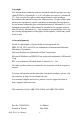
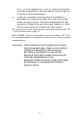
Boards are 20W, that means the ARK-5280 can only works under the maximum of ambient temperature of 30°C. Figure 1.1: PCI Board Power Consumption Limit Relative humidity 95 % @ 40° C (non-condensing) Vibration loading during operation • When system is equipped with Industrial grade Compact Flash Disk: 5Grms, IEC 60068-2-64, random, 5~500Hz, 1 oct./min, 1hr/axis. • When system is equipped with 2.5-inch hard disk: 1Grms, IEC 60068-2-64, random, 5~500Hz, 1 oct./min, 1hr/axis.
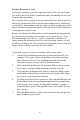
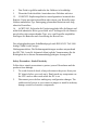
90.00 137.00 234.00 189.00 215.00 234.00 90.00 221.00 10.00 R2 .5 0 R5.5 0 35.50 1.4 Chassis Dimensions 7.00 Figure 1.
ARK-5280 User Manual 8
CHAPTER 2 2 Hardware Functionality This chapter shows how to set up the ARK5280’s hardware functions, including connecting peripherals, switches and indicators.
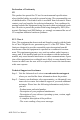
Chapter 2 Hardware Functionality 2.1 Introduction of External I/O Connectors The following two figures show the external I/O connectors on ARK5280. The following sections give you detailed information about functions of each I/O connector. Figure 2.1: Front Panel External I/O Connectors 2.2 Front Panel External I/O Connectors 2.2.1 Power ON/OFF Button The ARK-5280 comes with a Power On/Off button that supports the dual function of Soft Power -On/Off (Instant off or Delay 4 Second), and Suspend. 2.2.
LED is for hard disk and compact flash disk status, which flashes in red color. 2.2.3 Power Input Connector The ARK-5280 comes with a 4-pole DIN-jack that carries 9~35 VDC external power input. Please refer to Table 2.1 for their pin assignments. 2 1 3 4 Figure 2.2: 4-pole, DC DIN-Jack Table 2.1: Power Connector Pin Assignments Pin Signal Name 1 +9~35VDC 2 +9~35VDC 3 GND 4 GND 2.2.
1 DCD Tx- DATA- 2 RxD Tx+ DATA+ 3 TxD Rx+ NC 4 DTR Rx- NC 5 GND GND GND 6 DSR NC NC 7 RTS NC NC 8 CTS NC NC 9 RI NC NC Note: NC represents “No Connection” 2.2.5 COM1, COM3, and COM4 Connector The ARK-5280 provides three-RS-232 ports by three D-sub 9-pin connectors. Please refer to Table 2.3 for their pin assignments. 1 2 3 4 5 6 7 8 9 Figure 2.4: COM1, COM3 and COM 4 Connector Table 2.
8 CTS 9 RI 2.2.6 Audio Connector The ARK-5280 offers AC97 stereo Audio output ports by three phone jack (3.5, 5P, 90D(F) connectors of Line_In (BLUE color), Speaker_Out (LIME color) and Mic_In (Pink color). Line-In Connector Footprint Phone Jack 3.5Ø 5P, 90°, Female, BLUE color, Shielded Speaker-Out Connector Footprint Phone Jack 3.5Ø 5P, 90°, Female, LIME color, Shielded Mic-In Connector Footprint Phone Jack 3.5Ø 5P, 90°, Female, PINK color, Shielded 2.2.
14 15 16 17 18 19 22 23 24 C5 VCC_DVI GND HP_DET TMDS_C0# TMDS_C0 GND GND TMDS_CK TMDS_CK# GND 2.2.8 Ethernet Connector (LAN) The ARK-5280 is equipped with an Intel 82551ER Ethernet controller that is fully compliant with IEEE 802.3u 10/100Base-T CSMA/CD standards. The Ethernet port provides a standard RJ-45 jack connector with LED indicators on the front side to show its Active/Link status (Green LED) and Speed status (white LED). 1 8 Figure 2.6: RJ-45 Connector Table 2.
6 RCV- 7 NC 8 NC Note: NC represents “No Connection” 2.2.9 PS2 Keyboard/Mouse Connector The ARK-5280 provides a PS2 keyboard/mouse connector. A 6-pin miniDIN connector is located on the front panel of the ARK-5280. The ARK5280 comes with an adapter to convert from the 6-pin mini-DIN connector to two 6-pin mini-DIN connectors for PS2 keyboard and PS2 mouse connection. Please refer to Table 2.9 for its pin assignments. 6 5 4 3 2 1 Figure 2.7: PS/2 Mouse Connector Table 2.
2.2.10 VGA Connector The ARK-5280 provides a high resolution VGA interface via D-sub 15pin connector to support a VGA CRT monitor. It supports VGA and VESA, up to 1600 x 1200 @ 85-Hz resolution and up to 32 MB shared memory. 5 1 10 6 15 11 Figure 2.8: VGA Connector Table 2.7: Table 2.10: VGA port pin assignments Pin Signal Name Pin Signal Name 1 RED 9 NC 2 GREEN 10 GND 3 BLUE 11 NC 4 NC 12 DDC DATA 5 GND 13 H-SYNC 6 GND 14 V-SYNC 7 GND 15 DDC CLOCK 8 GND 2.2.
The USB-interface connector is used for connecting any device that conforms to the USB interface. Many recent digital devices conform to this standard. The USB interface supports Plug and Play, which enables you to connect or disconnect a device whenever you want, without turning off the computer. Figure 2.9: USB Connector Table 2.
ARK-5280 User Manual 18
CHAPTER 3 2 Hardware Installation & Upgrade This chapter introduces how to initialize the ARK-5280. Sections include: • Jumpers and Connectors • Connecting power • DDR SDRAM Installation • Compact Flash Card insertion • 2.
Chapter 3 Hardware Installation & Upgrade 3.1 Jumpers and Connectors The ARK-5280 Embedded Box Computer consists of an Advantech SBC (Single Board Computer) board that is housed in an aluminum top cover, a metal chassis with accessed bottom plate. Your CPU, HDD and SDRAM, are all readily accessible by removing the aluminum top cover. Any maintenance or hardware upgrades can be easily completed after removing the top cover or the accessed bottom plate.
A pair of needle-nose pliers may be helpful when working with jumpers. If you have any doubts about the best hardware configuration for your application, contact your local distributor or sales representative before you make any changes. 3.3 Jumper Location The ARK-5280 Embedded Box Computer has a number of jumpers inside the chassis that allows you to configure your system to suit your application. The table below lists the functions of the various jumpers. Table 3.
3.4 COM2 RS-232/422/485 Jumper setting (JP1) The COM2 port located on front metal face plate of ARK-5280 unit can be configured to operate in RS-232, RS-422 or RS-485 mode by setting up the Jumper Pins of JP1 located on internal motherboard. Table 3.2: COM2 RS-232/422/485 Jumper Selection Function Pin Setting RS-232 * 1-2 closed* RS-422 3-4 closed RS-485 5-6 closed (*): means default setting of the jumper/function 3.
3.6 PCl Card Power Selection Table 3.4: PCl Card Power Selection Function Pin Setting +5V * 1-2 closed* +3.3V 2-3 closed (*): means default setting of the jumper/function 3.7 Connecting Power Connect the ARK-5280 to a 9~32.5 VDC power source. The power source can either be from a power adapter or an in-house power source. 3.8 Installing the DDR SDRAM Memory Module The ARK-5280 provides two 200-pin SODIMM (Small Outline Dual Inline Memory Module) sockets and supports 2.5V DDR SDRAM*.
Figure 3.3: Unscrew the Top Cover Screws 3. Remove the top cover and PCI cover. Figure 3.4: Remove the Top Cover and PCI Cover 4.
Figure 3.5: Insert the SODIMM Module 5. Reverse the steps and assemble the ARK-5280. Note: There are two SODIMM sockets at each side of M/B. Here only shows the M/B bottom side SODIMM installation. Please contact your distributor or sales representative if you want to install the other SODIMM. 3.9 Install a Compact Flash Card The procedure for installing a Compact Flash card into the ARK-5280 is detailed below, please follow these steps carefully. 1. Remove the power cord. (Please see Figure 8.1) 2.
4. Install the CF card into the CF socket. Figure 3.6: Install the CF Card 5. Reverse the steps and assemble the ARK-5280. Note: The CompactFlash card socket is allocated as Secondary IDE Master. 3.10 Installing the 2.5" Hard Disk Drive (HDD) You can attach one enhanced Integrated Device Electronics (IDE) hard disk drive to the ARK-5280's internal controller which uses a PCI localbus interface. The advanced IDE controller supports faster data transfer and allows the IDE hard drive to exceed 528 MB.
3. Remove the top cover and PCI cover. 4. Unscrew the HDD cover frame screws and remove the cover frame. Figure 3.7: Remove the HDD cover frame 5. Connect the HDD and IDE cable Figure 3.
6. Install the HDD into the HDD housing. Figure 3.9: Install the HDD into the HDD Housing 7. Reverse steps 4 ~ step 1 to assemble ARK-5280. 3.11 Installing the PCI card The ARK-5280 provides two PCI slots for extension. The procedure of installing the PCI extension card into the ARK-5280 is detailed below, please follow these steps carefully. 1. Remove the power cord. 2. Unscrew the two screws from the top cover and remove the top cover. 3. Remove the top cover and PCI cover. 4.
Figure 3.10: Remove the PCI dummy bracket 5. Insert the PCI card into the PCI slot and fasten the screw.
Figure 3.11: Insert the PCI Card and Fasten 6. Adjust the depressed rubber height to fit the PCI extension card. Rotate the rubber to adjust its height Figure 3.12: Adjust the Depressed Rubber Height 7. Reverse steps 4 ~ step 1 to assemble ARK-5280.
CHAPTER 4 2 BIOS Setup This chapter introduces how to setup the BIOS of the ARK-5280.
Chapter 4 Award BIOS Setup 4.1 Introduction Award’s BIOS ROM has a built-in setup program that allows users to modify the basic system configuration. This information is stored in a battery-backed memory (CMOS RAM) so that it retains the setup information when the power is turned off. 4.1.1 CMOS RAM Auto-backup and Restore The CMOS RAM is powered by an onboard button cell battery. When you finish BIOS setup, the data in CMOS RAM will be automatically backed up to Flash ROM.
Figure 4.1: Award BIOS Setup 4.3 Standard CMOS Setup Choose the “Standard CMOS Features” option from the “Initial Setup Screen” menu, and the screen below will be displayed. This menu allows users to configure system components such as date, time, hard disk drive, floppy drive, display, and memory.
Figure 4.2: Standard CMOS Features 4.4 Advanced BIOS Features The “Advanced BIOS Features” screen appears when choosing the “Advanced BIOS Features” item from the “Initial Setup Screen” menu. It allows the user to configure the ARK-5280 according to their particular requirements. Below are some major items that are provided in the Advanced BIOS Features screen. A quick booting function is provided for your convenience.
Figure 4.3: Advanced BIOS Features 4.4.1 Virus Warning If enabled, a warning message and alarm beep activates if someone attempts to write here. The commands are “Enabled” or “Disabled.” 4.4.2 L1 & L2 Cache Enabling this feature speeds up memory access. The commands are “Enabled” or “Disabled.” 4.4.3 Quick Power On Self Test This option speeds up the Power-On Self Test (POST) conducted as soon as the computer is turned on. When Enabled, BIOS shortens or skips some of the items during the test.
4.4.6 Boot UP Floppy Seek Selection of the command “Disabled” will speed the boot up. Selection of “Enabled” searches disk drives during boot up. 4.4.7 Boot Up NumLock Status This feature selects the “power on” state for NumLock. The commands are “Enabled” or “Disabled.” 4.4.8 Gate A20 Option Normal: A pin in keyboard controller controls GateA20 Fast (Default): Chipset controls GateA20. 4.4.
4.4.13 APIC Mode This setting allows selecting an OS with greater than 64MB of RAM.Commands are “Non-OS2” or “OS2.” 4.4.14 MPS Version Control For OS This reports if an FDD is available for Windows 95. The commands are “Yes” or “No.” 4.5 Advanced Chipset Features The “Advanced Chipset Features” screen appears when choosing the “Advanced Chipset Features” item from the “Initial Setup Screen” menu. It allows the user to configure the system chipset according to his particular requirements.
DRAM installed. Do not change the values in this field unless you change specifications of the installed DRAM or the installed CPU. 4.5.3 Active to Precharge Delay The default setting for the Active to Precharge Delay is 7. 4.5.4 DRAM RAS# to CAS# Delay This option allows you to insert a delay between the RAS (Row Address Strobe) and CAS (Column Address Strobe) signals. This delay occurs when the SDRAM is written to, read from or refreshed. Reducing the delay improves the performance of the SDRAM. 4.5.
4.5.11 Delayed Transaction The chipset has an embedded 32-bit posted write buffer to support delay transactions cycles. Select Enabled to support compliance with PCI specification version 2.1. 4.5.12 Delay Prior to Thermal This field activates the CPU thermal function after the systems boots for the set number of minutes. The options are 16Min and 64Min. 4.5.13 AGP Aperture Size (MB) The field sets aperture size of the graphics.
4.5.16 Boot Display The default setting is VBIOS Default. The options available include CRT, LVDS, DVI and TV. 4.5.17 Panel Scaling The default setting is Auto. The options available include On and Off. 4.5.18 Panel Resolution These fields allow you to select the LCD Panel type. The default values for these ports are: • 640 x 480 • 800 x 600 • 1024 x 768 • 1280 x 1024 • 1600 x 1200 Figure 4.
Figure 4.7: “Panel Number” (Resolution) Selection 4.6 Integrated Peripherals This section sets configurations for your hard disk and other integrated peripherals. The first screen shows three main items for user to select. Once an item selected, a submenu appears. Details follow. Figure 4.
4.6.1 IDE Master/Slave PIO/UDMA Mode, IDE Primary (Secondary) Master/Slave PIO/UDMA Mode (Auto) Each channel (Primary and Secondary) has both a master and a slave, making four IDE devices possible. Because each IDE device may have a different Mode timing (0, 1, 2, 3, 4), it is necessary for these to be independent. The default setting “Auto” will allow auto detection to ensure optimal performance. 4.6.
Figure 4.10: Onboard Device 4.6.4 USB Controller Select Enabled if your system contains a Universal Serial Bus (USB) controller and you have USB peripherals. The choices: Enabled, Disabled. 4.6.5 USB 2.0 Controller The options for this field are Enabled and Disabled. By default, this field is set to Enabled. In order to use USB 2.0, necessary OS drivers must be installed first. Please update your system to Windows 2000 SP4 or Windows XP SP1. 4.6.
Figure 4.11: Super IO Device 4.6.9 Onboard FDC Controller When enabled, this field allows you to connect your floppy disk drives to the onboard floppy disk drive connector instead of a separate controller card. If you want to use a different controller card to connect the floppy disk drives, set this field to Disabled. 4.6.10 Onboard Serial Port These fields allow you to select the IRQ of onboard serial port with their addresses, or you can select Disabled.
4.6.14 UR2 Duplex Mode This item allows you to select the IR half/full duplex function. The choices: Half, Full. 4.6.15 Onboard Parallel Port This field sets the address of the on-board parallel port connector. These fields allow you to select the IRQ of onboard serial port with their addresses, or you can select Disabled. The default values for parallel ports are: 378/IRQ7 4.6.16 Parallel Port Mode This field allows you to set the operation mode of the parallel port.
Former-Sts When power returns after an AC power failure, the system will return to the state where you left off before power failure occurs. If the system’s power is off when AC power failure occurs, it will remain off when power returns. If the system’s power is on when AC power failure occurs, the system will power on when power returns. 4.7 Power Management Setup The Power Management Setup allows you to configure your system to most effectively to save energy. 4.7.
Figure 4.12: Power Management Setup 4.7.4 Video Off In Method This determines the manner in which the monitor is blanked. V/H SYNC + Blank This will cause the system to turn off the vertical and horizontal synchronization ports and write blanks to the video buffer. Blank Screen This only writes blanks to the video buffer. DPMS Support Initializes display power management signaling. Select this if your video board supports it. 4.7.5 Video Off In Suspend When system is in suspend, video will turn off.
4.7.9 HDD Power Down You can choose to turn the HDD off after one of the time intervals listed, or when the system is in “suspend” mode. If the HDD is in a power saving mode, any access to it will wake it up. 4.7.10 Soft-Off by PWR-BTTN If you choose “Instant-Off”, then pushing the ATX soft power switch button once will switch the system to “system off” power mode. You can choose “Delay 4 sec.
4.7.15 Primary IDE 0 (1) and Secondary IDE 0 (1) When Enabled, the system will resume from suspend mode if Primary IDE 0 (1) or Secondary IDE 0 (1) is active. The choice: Enabled, Disabled. 4.7.16 FDD, COM, LPT PORT When Enabled, the system will resume from suspend mode if FDD, COM port, or LPT port is active. The choice: Enabled, Disabled. 4.7.17 PCI PIRQ [A-D]# When Enabled, the system will resume from suspend mode if interrupt occurs. The choice: Enabled, Disabled. 4.
4.8.1 Reset Configuration Data Default is Disable. Select Enable to reset Extended System Configuration Data (ESCD) if you have installed a new add-on and system e configuration has caused such a conflict that OS cannot boot. 4.8.2 Resources controlled by: The commands here are “Auto” or “Manual.” Choosing “manual” requires you to choose resources from each following sub-menu. “Auto” automatically configures all of the boot and Plug and Play devices but you must be using Windows 95 or above. 4.8.
4.9.1 CPU Warning Temperature This field allows the user to set the temperature so that when the temperature is reached, the system sounds a warning. This function can help prevent damage to the system that is caused by overheating. 4.9.2 Temperatures/Voltages These fields are the parameters of the hardware monitoring function feature of the motherboard. The values are read-only values as monitored by the system and show the PC health status. 4.9.
4.11 Password Setting To change the password: 1. Choose the “Set Password” option from the “Initial Setup Screen” menu and press .The screen will display the following message: Please Enter Your Password Press 2. If the CMOS is good or if this option has been used to change the default password, the user is asked for the password stored in the CMOS. The screen will display the following message: Please Confirm Your Password Enter the current password and press . 3.
CHAPTER 5 2 PCI-SVGA Setup Sections include: • Introduction • Installation of SVGA drivers-for Windows 2000/XP • Further information
Chapter 5 PCI SVGA Setup 5.1 Introduction The board has an onboard interface. The specifications and features are described as follows: 5.1.1 Chipset The ARK-5280 uses a Intel 855GME + 6300ESB chipset for its graphic controller. It supports LVDS LCD displays, conventional CRT monitors. 5.1.
1. Select the path: D:\2_VGA, then double click “win2k_xp141” to run “Install Shield Wizard” Figure 5.1: Directory of VGA Driver Note: 1. The windows illustrations in this chapter are intended as examples only. Please follow the listed steps, and pay attention to the instructions which appear on your screen. 2. For convenience, the CD-ROM drive is designated as “D” throughout this chapter. 2. Press the “Next” button.
Figure 5.2: VGA Driver Installation Setup Screen 3. Press the “Next” button. Figure 5.
4. In order to continue setup, you must accept the agreement. Figure 5.4: License Agreement 5. Choose the option “Yes, I want to restart my computer now.” Figure 5.
5.3 Further information For further information about the AGP/VGA installation in your ARK5280, including driver updates, troubleshooting guides and FAQ lists, visit the following web resources: Intel website: www.intel.com Advantech websites: www.advantech.com, or www.advantech.com.
CHAPTER 6 2 PCI Bus Ethernet Interface The chapter provides information on Ethernet configuration.
Chapter 6 PCI Bus Ethernet Interface 6.1 Introduction The board is equipped with a high performance 32-bit Ethernet chipset which is fully compliant with 802.3u 100BASE-T or 802.3z/ab 1000BASE-T. It is supported by major network operating systems. It is also both 100Base-T and 10Base-T compatible. The Ethernet port provides a standard RJ-45 jack. The network boot feature can be utilized by incorporating the boot ROM image files for the appropriate network operating system.
6.2.1 Installation for Windows XP Select ”Ethernet Controller” from Device Manager. Figure 6.1: Device Manager Select “Update Driver”.
Figure 6.2: Update Driver Click the “Next” button. Figure 6.3: Hardware Update Wizard Click the “Next” button.
Figure 6.4: Choose Automatic Installation Please choose “Continue Anyway”. Figure 6.5: Hardware Installation Click the “Finish” button.
Figure 6.
CHAPTER 7 2 Audio Setup Sections include: • Introduction • Installation of Audio drivers for Windows XP
Chapter 7 Audio Setup 7.1 Introduction The ARK-5280’s audio interface provides high-quality stereo sound and FM music synthesis (ESFM) by using the Intel ICH4 audio controller. The audio interface can record, compress, and play back voice, sound, and music with built-in mixer control. 7.2 Driver Installation 7.2.1 Before you begin Please read the instructions in this chapter carefully before you attempt installation. The audio drivers for the ARK-5280 board are located on the audio driver CD.
1. Select the path: D:\wdm_a357, then double click to run “Install Shield Wizard”. Figure 7.1: Audio Driver Directory 2. Press the “Next” button and wait for a moment.
Figure 7.2: Realtek AC’97 Audio Setup 3. Choose the option “Continue Anyway”. Figure 7.
4. Choose the option “Yes, I want to restart my computer now”, then click “Finish” button to reboot your computer. Figure 7.
ARK-5280 User Manual 70
A APPENDIX 2 Watchdog Timer The ARK-5280 is equipped with a watchdog timer that resets the CPU if processing comes to a standstill for any reason. This feature ensures system reliability in industrial standalone or unmanned environments.
Appendix A Watchdog Timer A.1 Watchdog Programming The ARK-5280 Embedded Box Computer is equipped with a watchdog timer that resets the CPU if processing comes to a standstill for any reason. This feature ensures system reliability in industrial standalone or unmanned environments. Below is the programming sample of Watchdog.