
User manual
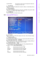
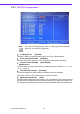
Table Of Contents
- ARK-3399
- 1 General Introduction
- 2 H/W installation
- 2.1 Introduction
- 2.2 Jumpers
- 2.3 Connectors
- Figure 2.2 ARK-3389 IO connectors drawing
- 2.3.1 ARK-3399 external I/O connectors
- 2.3.1.1 COM Connectors
- 2.3.1.2 Ethernet Connector (LAN)
- 2.3.1.3 PS2 Keyboard/Mouse Connector
- 2.3.1.4 VGA Connector
- 2.3.1.5 USB Connector
- 2.3.1.6 Power Input Connector
- 2.3.1.7 Power ON/OFF Button
- 2.3.1.8 LED Indicators
- 2.3.1.9 Audio Connector
- 2.3.1.10 DIO Connector
- 2.3.1.11 LVDS Connector
- 2.3.1.12 LCD Backlight On/Off control Connector
- 2.4 Installation
- 3 BIOS Operation
- 3.1 BIOS Introduction
- 3.2 BIOS Setup
- 3.2.1 Main Menu
- 3.2.2 Standard CMOS Features
- 3.2.3 Advanced BIOS Features
- 3.2.4 Advanced Chipset Features
- 3.2.5 Integrated Peripherals
- 3.2.6 Power Management Setup
- 3.2.7 PnP/PCI Configurations
- 3.2.8 PC Health Status
- 3.2.9 Frequency/Voltage Control
- 3.2.10 Load Optimized Defaults
- 3.2.11 Set Password
- 3.2.12 Save & Exit Setup
- 3.2.13 Quit Without Saving
- 4 Full Disassembly Procedure
- 4.1 Introduction
- Figure 4.1 Unscrew the bottom screws
- Figure 4.2 Unscrew the frame screws and remove the frame
- Figure 4.3 Unscrew the panel screws
- Figure 4.4 Unscrew the hex-bolts on the panel
- Figure 4.5 Unscrew the ground wire of LVDS cable and disconnect all the cables and boards
- Figure 4.6 Unscrew the boards’ screws and hex-bolts for disassembly
- Figure 4.7 Unscrew the power module screws on the bottom to disassemble the power module
- 4.1 Introduction
ARK-3399 User Manual 32
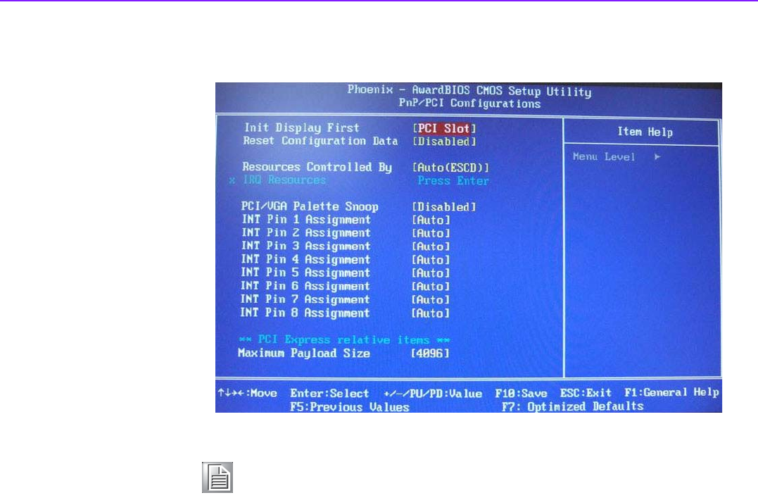
3.2.7 PnP/PCI Configurations
Init Display First [PCI Slot]
This item is setting for start up Video output from PCI or Onboard device.
Reset Configuration Data [Disabled]
This item allow user to clear any PnP configuration data stored in the BIOS.
Resources Controlled By [Auto (ESCD)]
IRQ Resources
This item allows you respectively assign an interruptive type for IRQ-3, 4, 5, 7, 9, 10,
11, 12, 14, and 15.
PCI VGA Palette Snoop [Disabled]
The item is designed to solve problems caused by some non-standard
VGA cards. A built-in VGA system does not need this function.
Maximum Payload Size [4096]
This BIOS feature determines the maximum TLP (Transaction Layer Packet) payload
size that can be supported by the motherboard chipset's PCI Express controller. The
TLP payload size determines the amount of data transmitted within each data packet.
Note! This “PnP/PCI Configurations” option is setting up the IRQ and DMA
(both PnP and PCI bus assignments.