
User manual
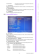
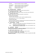
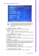
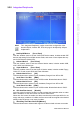
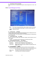
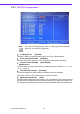
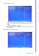
Table Of Contents
- ARK-3399
- 1 General Introduction
- 2 H/W installation
- 2.1 Introduction
- 2.2 Jumpers
- 2.3 Connectors
- Figure 2.2 ARK-3389 IO connectors drawing
- 2.3.1 ARK-3399 external I/O connectors
- 2.3.1.1 COM Connectors
- 2.3.1.2 Ethernet Connector (LAN)
- 2.3.1.3 PS2 Keyboard/Mouse Connector
- 2.3.1.4 VGA Connector
- 2.3.1.5 USB Connector
- 2.3.1.6 Power Input Connector
- 2.3.1.7 Power ON/OFF Button
- 2.3.1.8 LED Indicators
- 2.3.1.9 Audio Connector
- 2.3.1.10 DIO Connector
- 2.3.1.11 LVDS Connector
- 2.3.1.12 LCD Backlight On/Off control Connector
- 2.4 Installation
- 3 BIOS Operation
- 3.1 BIOS Introduction
- 3.2 BIOS Setup
- 3.2.1 Main Menu
- 3.2.2 Standard CMOS Features
- 3.2.3 Advanced BIOS Features
- 3.2.4 Advanced Chipset Features
- 3.2.5 Integrated Peripherals
- 3.2.6 Power Management Setup
- 3.2.7 PnP/PCI Configurations
- 3.2.8 PC Health Status
- 3.2.9 Frequency/Voltage Control
- 3.2.10 Load Optimized Defaults
- 3.2.11 Set Password
- 3.2.12 Save & Exit Setup
- 3.2.13 Quit Without Saving
- 4 Full Disassembly Procedure
- 4.1 Introduction
- Figure 4.1 Unscrew the bottom screws
- Figure 4.2 Unscrew the frame screws and remove the frame
- Figure 4.3 Unscrew the panel screws
- Figure 4.4 Unscrew the hex-bolts on the panel
- Figure 4.5 Unscrew the ground wire of LVDS cable and disconnect all the cables and boards
- Figure 4.6 Unscrew the boards’ screws and hex-bolts for disassembly
- Figure 4.7 Unscrew the power module screws on the bottom to disassemble the power module
- 4.1 Introduction
ARK-3399 User Manual 30
Watch Dog Timer-Out Value[00]
This item allows user to enabled watch dog time of value, Range is from 10 sec ~ 255
Min.
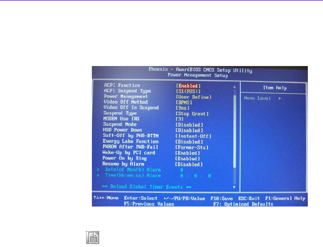
3.2.6 Power Management Setup
ACPI Function [Enabled]
This item defines the ACPI (Advanced Configuration and Power Management) fea-
ture that makes hardware status information available to
the operating system, and communicate PC and system devices for improving the
power management.
ACPI Suspend Type [S1 (POS)]
This item allows user to select sleep state when suspend, but this System only can
use S1 Mode.
S1(POS) The suspend mode is equivalent to a software power down;
Power Management Option [User Define]
This item allows user to select system power saving mode.
Min Saving Minimum power management. Suspend Mode=1 hr.
Max Saving Maximum power management. Suspend Mode=1 min.
User Define Allows user to set each mode individually. Suspend Mode= Dis-
abled or 1 min ~1 hr.
Video Off Method [DPMS]
This item allows user to determine the manner is which the monitor is blanked.
V/H SYNC+BlankThis option will cause system to turn off vertical and horizontal
synchronization ports and write blanks to the video buffer.
Blank Screen This option only writes blanks to the video buffer.
DPMS Initial display power management signaling.
Note! This “Power management Setup” option configure system to most effec-
tively saving energy while operating in a manner consistent with your
computer use style.