
User manual
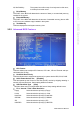
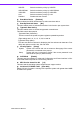
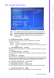
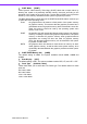
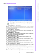
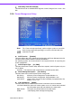
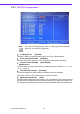
Table Of Contents
- ARK-3399
- 1 General Introduction
- 2 H/W installation
- 2.1 Introduction
- 2.2 Jumpers
- 2.3 Connectors
- Figure 2.2 ARK-3389 IO connectors drawing
- 2.3.1 ARK-3399 external I/O connectors
- 2.3.1.1 COM Connectors
- 2.3.1.2 Ethernet Connector (LAN)
- 2.3.1.3 PS2 Keyboard/Mouse Connector
- 2.3.1.4 VGA Connector
- 2.3.1.5 USB Connector
- 2.3.1.6 Power Input Connector
- 2.3.1.7 Power ON/OFF Button
- 2.3.1.8 LED Indicators
- 2.3.1.9 Audio Connector
- 2.3.1.10 DIO Connector
- 2.3.1.11 LVDS Connector
- 2.3.1.12 LCD Backlight On/Off control Connector
- 2.4 Installation
- 3 BIOS Operation
- 3.1 BIOS Introduction
- 3.2 BIOS Setup
- 3.2.1 Main Menu
- 3.2.2 Standard CMOS Features
- 3.2.3 Advanced BIOS Features
- 3.2.4 Advanced Chipset Features
- 3.2.5 Integrated Peripherals
- 3.2.6 Power Management Setup
- 3.2.7 PnP/PCI Configurations
- 3.2.8 PC Health Status
- 3.2.9 Frequency/Voltage Control
- 3.2.10 Load Optimized Defaults
- 3.2.11 Set Password
- 3.2.12 Save & Exit Setup
- 3.2.13 Quit Without Saving
- 4 Full Disassembly Procedure
- 4.1 Introduction
- Figure 4.1 Unscrew the bottom screws
- Figure 4.2 Unscrew the frame screws and remove the frame
- Figure 4.3 Unscrew the panel screws
- Figure 4.4 Unscrew the hex-bolts on the panel
- Figure 4.5 Unscrew the ground wire of LVDS cable and disconnect all the cables and boards
- Figure 4.6 Unscrew the boards’ screws and hex-bolts for disassembly
- Figure 4.7 Unscrew the power module screws on the bottom to disassemble the power module
- 4.1 Introduction
29 ARK-3399 User Manual
Chapter 3 BIOS Operation
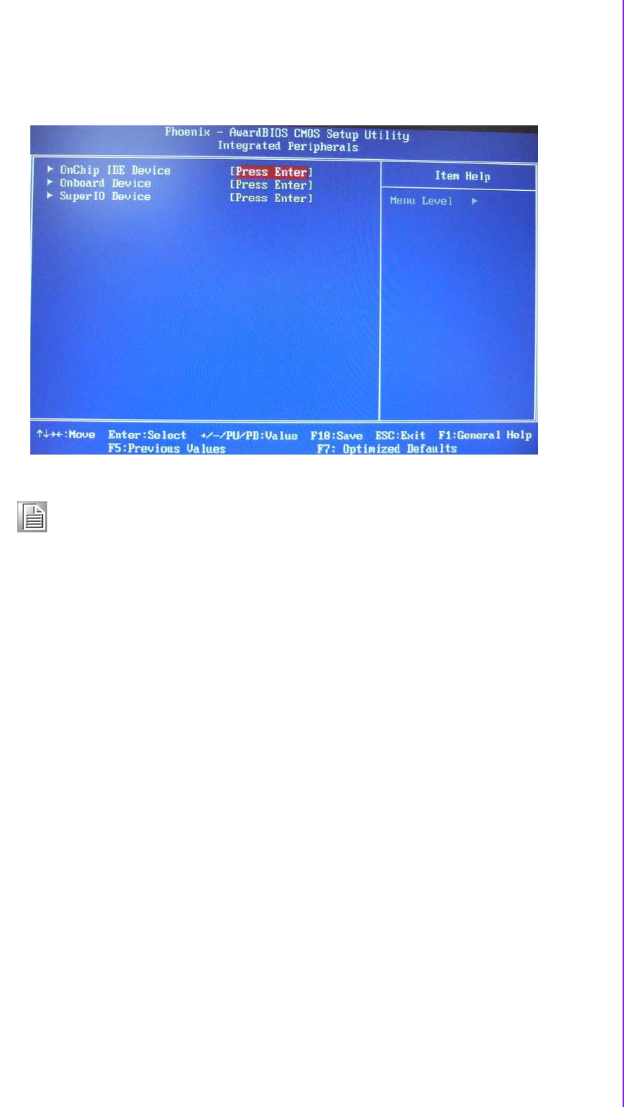
3.2.5 Integrated Peripherals
OnChip IDE Device [Press Enter]
This item enables users to set the OnChip IDE device status, includes enable IDE
devices and setting PIO and DMA access mode, and some of new chipset also sup-
port for SATA device (Serial-ATA).
Onboard Device [Press Enter]
This item enables users to set the Onboard device status, includes enable USB,
AC97, MC97 and LAN devices.
Super IO Device [Press Enter]
This item enables users to set the Super IO device status, includes enable Floppy,
COM, LPT, IR and control GPIO and Power fail status.
Onboard Serial Port 1 [3F8]
This item allows user to select I/O port of address, Range is from 2E8 to 3F8.
Serial Port 1 Use IRQ [IRQ4]
This item allows user to select I/O port of IRQ number. Bios default value is “IRQ4”.
Onboard Serial Port 2 [2F8]
This item allows user to select I/O port of address, Range is from 2E8 to 3F8.
Serial Port 2 Use IRQ [IRQ3]
This item allows user to select I/O port of IRQ number. Bios default value is “IRQ3”.
SP2 AutoFlow Control [Disable]
Auto flow control is used in RS-485, is used to tristate the transmitter when no other
data is available, so that other nodes can use the shared lines.
When auto flow control is enable, the device monitors the local output buffer for not
empty and empty conditions. If enable, the flow control will force signal to the desired
polarity under the empty or not empty condition.
Watch Dog Timer-Out Value Unit[Minutes]
This item allows user to select watch dog time of value unit with minutes or seconds.
Note! This “Integrated Peripherals” option controls the configuration of the
boardís chipset, includes IDE, ATA, this page is developed by Chipset
independent.