
User manual
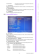
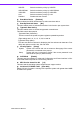
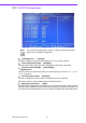
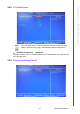
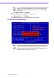
Table Of Contents
- ARK-3399
- 1 General Introduction
- 2 H/W installation
- 2.1 Introduction
- 2.2 Jumpers
- 2.3 Connectors
- Figure 2.2 ARK-3389 IO connectors drawing
- 2.3.1 ARK-3399 external I/O connectors
- 2.3.1.1 COM Connectors
- 2.3.1.2 Ethernet Connector (LAN)
- 2.3.1.3 PS2 Keyboard/Mouse Connector
- 2.3.1.4 VGA Connector
- 2.3.1.5 USB Connector
- 2.3.1.6 Power Input Connector
- 2.3.1.7 Power ON/OFF Button
- 2.3.1.8 LED Indicators
- 2.3.1.9 Audio Connector
- 2.3.1.10 DIO Connector
- 2.3.1.11 LVDS Connector
- 2.3.1.12 LCD Backlight On/Off control Connector
- 2.4 Installation
- 3 BIOS Operation
- 3.1 BIOS Introduction
- 3.2 BIOS Setup
- 3.2.1 Main Menu
- 3.2.2 Standard CMOS Features
- 3.2.3 Advanced BIOS Features
- 3.2.4 Advanced Chipset Features
- 3.2.5 Integrated Peripherals
- 3.2.6 Power Management Setup
- 3.2.7 PnP/PCI Configurations
- 3.2.8 PC Health Status
- 3.2.9 Frequency/Voltage Control
- 3.2.10 Load Optimized Defaults
- 3.2.11 Set Password
- 3.2.12 Save & Exit Setup
- 3.2.13 Quit Without Saving
- 4 Full Disassembly Procedure
- 4.1 Introduction
- Figure 4.1 Unscrew the bottom screws
- Figure 4.2 Unscrew the frame screws and remove the frame
- Figure 4.3 Unscrew the panel screws
- Figure 4.4 Unscrew the hex-bolts on the panel
- Figure 4.5 Unscrew the ground wire of LVDS cable and disconnect all the cables and boards
- Figure 4.6 Unscrew the boards’ screws and hex-bolts for disassembly
- Figure 4.7 Unscrew the power module screws on the bottom to disassemble the power module
- 4.1 Introduction

ARK-3399 User Manual 28
DVMT Mode [DVMT]
Intel's Dynamic Video Memory Technology (DVMT) takes that concept further by
allowing the system to dynamically allocate memory resources according to the
demands of the system at any point in time. The key idea in DVMT is to improve the
efficiency of the memory allocated to either system or graphics processor.
The BIOS feature that controls all this is the DVMT Mode BIOS feature. It allows you
to select the DVMT operating mode.
Fixed the graphics driver will reserve a fixed portion of the system memory
as graphics memory. This ensures that the graphics processor has a
guaranteed amount of graphics memory but the downside is once allo-
cated, this memory cannot be used by the operating system even
when it is not in use.
DVMT the graphics chip will dynamically allocate system memory as graphics
memory, according to system and graphics requirements. The system
memory is allocated as graphics memory when graphics-intensive
applications are running but when the need for graphics memory
drops, the allocated graphics memory can be released to the operat-
ing system for other uses.
BOTH the graphics driver will allocate a fixed amount of memory as dedi-
cated graphics memory, as well as allow more system memory to be
dynamically allocated between the graphics processor and the operat-
ing system.
DVMT/FIXED Memory Size [64MB]
The default setting is 64MB. The options available include 64MB, 128MB and
224MB.
Boot Display [CRT]
The default setting is CRT. The options available include CRT, LFP, and LFP + CRT.
Panel Type [640X480, 18bits]
These fields allow you to select the LCD Panel type. The default values for these
ports are:
640 x 480, 18bits
800 x 600 18bits
1024 x 768 18bits
1280 x 1024 48bits