
User manual
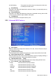
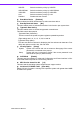
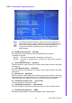
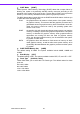
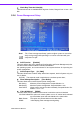
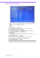
Table Of Contents
- ARK-3399
- 1 General Introduction
- 2 H/W installation
- 2.1 Introduction
- 2.2 Jumpers
- 2.3 Connectors
- Figure 2.2 ARK-3389 IO connectors drawing
- 2.3.1 ARK-3399 external I/O connectors
- 2.3.1.1 COM Connectors
- 2.3.1.2 Ethernet Connector (LAN)
- 2.3.1.3 PS2 Keyboard/Mouse Connector
- 2.3.1.4 VGA Connector
- 2.3.1.5 USB Connector
- 2.3.1.6 Power Input Connector
- 2.3.1.7 Power ON/OFF Button
- 2.3.1.8 LED Indicators
- 2.3.1.9 Audio Connector
- 2.3.1.10 DIO Connector
- 2.3.1.11 LVDS Connector
- 2.3.1.12 LCD Backlight On/Off control Connector
- 2.4 Installation
- 3 BIOS Operation
- 3.1 BIOS Introduction
- 3.2 BIOS Setup
- 3.2.1 Main Menu
- 3.2.2 Standard CMOS Features
- 3.2.3 Advanced BIOS Features
- 3.2.4 Advanced Chipset Features
- 3.2.5 Integrated Peripherals
- 3.2.6 Power Management Setup
- 3.2.7 PnP/PCI Configurations
- 3.2.8 PC Health Status
- 3.2.9 Frequency/Voltage Control
- 3.2.10 Load Optimized Defaults
- 3.2.11 Set Password
- 3.2.12 Save & Exit Setup
- 3.2.13 Quit Without Saving
- 4 Full Disassembly Procedure
- 4.1 Introduction
- Figure 4.1 Unscrew the bottom screws
- Figure 4.2 Unscrew the frame screws and remove the frame
- Figure 4.3 Unscrew the panel screws
- Figure 4.4 Unscrew the hex-bolts on the panel
- Figure 4.5 Unscrew the ground wire of LVDS cable and disconnect all the cables and boards
- Figure 4.6 Unscrew the boards’ screws and hex-bolts for disassembly
- Figure 4.7 Unscrew the power module screws on the bottom to disassemble the power module
- 4.1 Introduction
27 ARK-3399 User Manual
Chapter 3 BIOS Operation
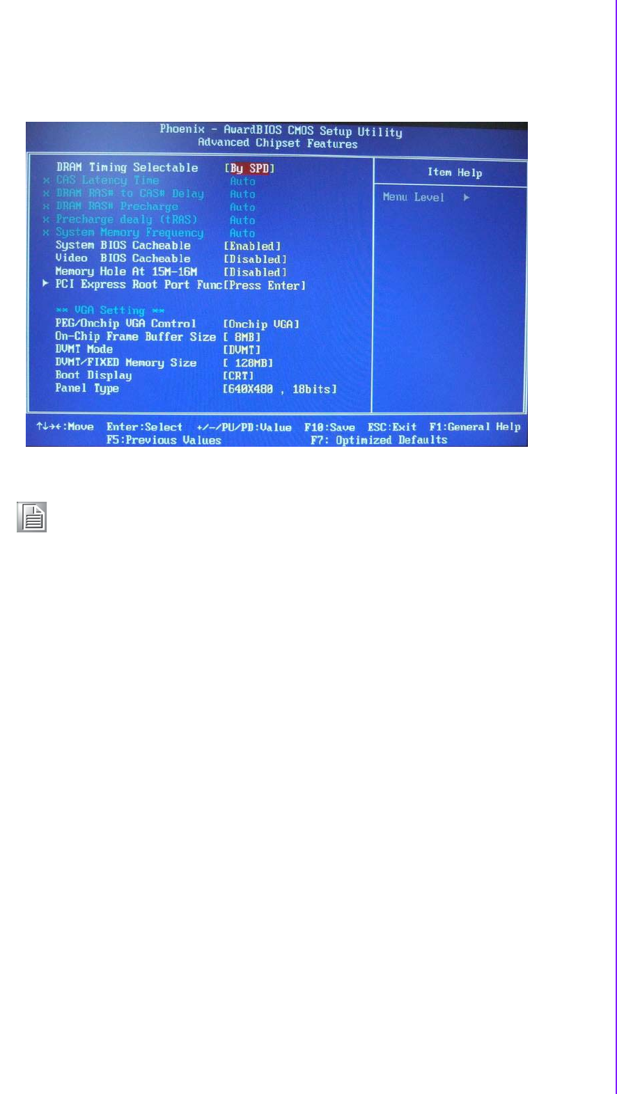
3.2.4 Advanced Chipset Features
DRAM Timing Selectable [By SPD]
This option refers to the method by which the DRAM timing is selected.
The default is “By SPD”.
Manual This item is provided dram clock/drive for User select.
By SPD This item is provided dram clock/drive for SPD (Serial Presence
Detect).
System BIOS Cacheable [Enabled]
This item allows the system BIOS to be cached to allow faster execution and better
performance.
Video BIOS Cacheable [Disabled]
This item allows the video BIOS to be cached to allow faster execution and better
performance.
Memory Hole [Disabled]
This item reserves 15MB-16MB memory address space to ISA expansion cards that
specifically require the setting. Memory from 15 MB-16 MB will be unavailable to the
system because of the expansion cards can only access memory at this area.
PCI Express Root Port Func [Press Enter]
This item is setting for PCI Express device.
PEG/Onchip VGA Control [Onchip VGA]
This item is setting for start up Video output from Add-on-Card or Onboard device.
On-Chip Frame Buffer Size [8MB]
The default setting is 8MB. The options available include 1 MB and 8 MB.
Note! This “Advanced Chipset Features” option controls the configuration of
the boardís chipset, this page is developed by Chipset independent, for
control chipset register setting and fine tune system performance. It is
strongly recommended only technical users make changes to the
default settings.